
Split concrete core sample cutting device and cutting method thereof

A concrete core sample and cutting device technology, which is applied in the direction of working accessories, manufacturing tools, stone processing equipment, etc., can solve the problems of concrete block vibration and displacement, low cutting efficiency, and two surfaces are not parallel, so as to improve practicability And applicability, safety performance improvement, mechanical energy consumption reduction effect

Pending Publication Date: 2019-05-28
马鞍山中鑫工程质量检测咨询有限公司
View PDF8 Cites 4 Cited by
  • Summary
  • Abstract
  • Description
  • Claims
  • Application Information

AI Technical Summary

Problems solved by technology

[0002] Concrete block is a building material widely used in construction engineering. It has the characteristics of light weight, convenient construction, thermal insulation, and low cost. During the implementation of the project, it is often necessary to cut the concrete block into the required size. This requires the use of a cutting device. The existing concrete cutting device mainly has the following defects: first, it is easy to cause the vibration and displacement of the concrete block during the cutting process. There is no effective limit device, and the cutting accuracy and size consistency cannot be guaranteed. Secondly, the existing cutting device requires manual cutting tools, which is relatively laborious, the cutting efficiency is very low, and only one surface can be cut at a time, and the monomer needs to be cut repeatedly, which leads to the concrete after cutting block, the two surfaces are not parallel, and after the cutting is completed, it needs to be polished again, which is time-consuming and laborious

Method used


Image

  • Split concrete core sample cutting device and cutting method thereof
  • Split concrete core sample cutting device and cutting method thereof
  • Split concrete core sample cutting device and cutting method thereof

Examples


Embodiment 1

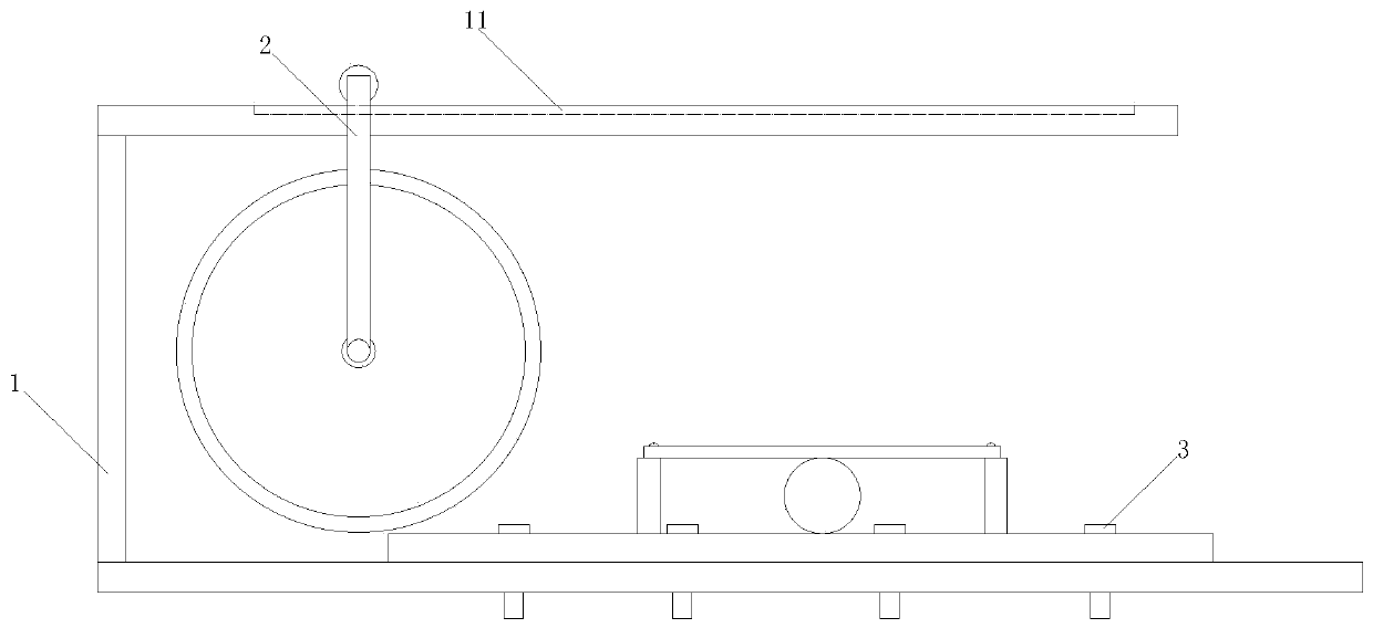
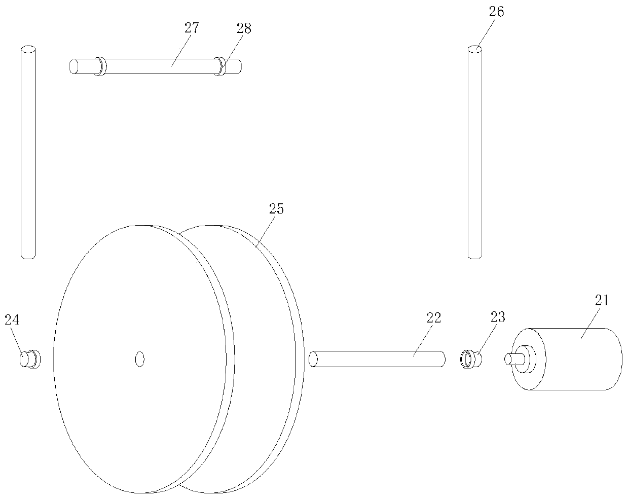
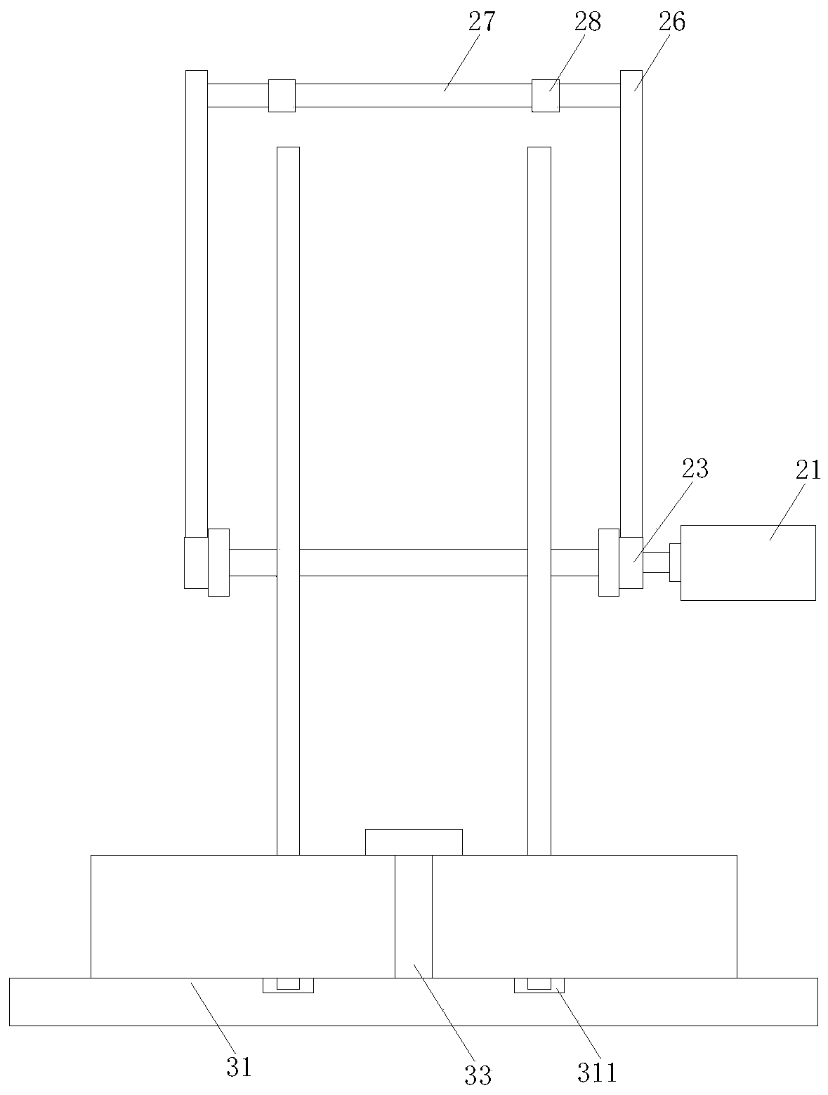
[0034] from figure 1 It can be seen that a double-parallel concrete core-like cutting device in this embodiment includes a workbench 1. A slideway 11 is provided on the upper surface of the workbench 1, and a cutting tool 2 is installed on the inner side of the slideway 11. figure 2 It can be seen that the cutting tool 2 is composed of a driving motor 21, a main shaft 22, a first bearing 23, a second bearing 24, a parallel blade 25, a connecting rod 26, a beam 27 and a roller 28, and the output end of the driving motor 21 is sleeved with a main shaft 22. The outer ring of the main shaft 22 is fixedly sleeved with a parallel blade 25. The parallel blade 25 is composed of two sets of parallel disc blades. The lower end of the blade extends to the inner side of the double blade groove 311. The inner groove surface of 311 is separated by 8mm-12mm to avoid the damage of the blade caused by the excessive cutting process. It has a protective effect on the concrete core sample and th...


PUM


Abstract

The invention discloses a split concrete core sample cutting device and a cutting method thereof, and belongs to the technical field of concrete processing. The split concrete core sample cutting device comprises a working table, wherein a slideway is arranged on an upper table surface of the working table; a cutting tool is arranged on the inner side of the slideway and is formed by a drive motor, a main shaft, a first bearing, a second bearing, a parallel type blade, a connecting rod, a cross beam and rollers; and a limited device is arranged on a lower table surface of the working table andis formed by a bottom plate, fixed bolts, adjustable bolts, a limited plate and pinned bolts. According to the split concrete core sample cutting device provided by the invention, double-cutter parallel-feeding type cutting is adopted for cutting two working surfaces of a concrete core sample at the same time, and after cutting, two processing surfaces are completely paralleled, so that the cutting period is shortened by half, and the production efficiency is effectively accelerated; and through screwing down or loosening the adjustable bolts, the space between the limited plate and the bottom plate can be further adjusted, so that the split concrete core sample cutting device can be matched with concrete core samples with different sizes, and the practicability and the applicability of the whole device are further improved.

Description

technical field [0001] The invention relates to the technical field of concrete processing, and more particularly, to a double-parallel concrete core-like cutting device and a cutting method thereof. Background technique [0002] Concrete block is a widely used building material in construction projects. It has the characteristics of light weight, convenient construction, thermal insulation, and low cost. In the process of project implementation, it is often necessary to cut concrete blocks into the required size. This requires the use of a cutting device. The existing concrete cutting devices mainly have the following defects: First, the concrete blocks are easily displaced by vibration during the cutting process, and there is no effective limit device to ensure the consistency of cutting accuracy and size. Secondly, the existing cutting device requires manual hand-held cutting tools, which is relatively laborious, and the cutting efficiency is very low, and only one surfac...

Claims


Application Information

Patent Timeline
IPC IPC(8): B28D1/24B28D7/02B28D7/04B28D7/00
Inventor 王琪陈苗苗孟小鹏张剑
Owner 马鞍山中鑫工程质量检测咨询有限公司
Learn More