Aircraft braked wheel rim

A technology for aircraft wheels and rims, applied in the directions of rims, wheels, wheels, etc., can solve the problems of increasing the risk of carbon oxidation of the brake disc and the weight of the equipment.

Active Publication Date: 2019-05-28
SAFRAN LANDING SYSTEMS
View PDF6 Cites 2 Cited by
  • Summary
  • Abstract
  • Description
  • Claims
  • Application Information

AI Technical Summary

Problems solved by technology

However, in addition to impeding access to the aircraft wheels for replacement or maintenance purposes, such equipment is heavy (typically several kilograms), a source of noise, and increases the risk of carbon oxidation of the brake discs

Method used


Image

  • Aircraft braked wheel rim
  • Aircraft braked wheel rim
  • Aircraft braked wheel rim

Examples


Embodiment Construction

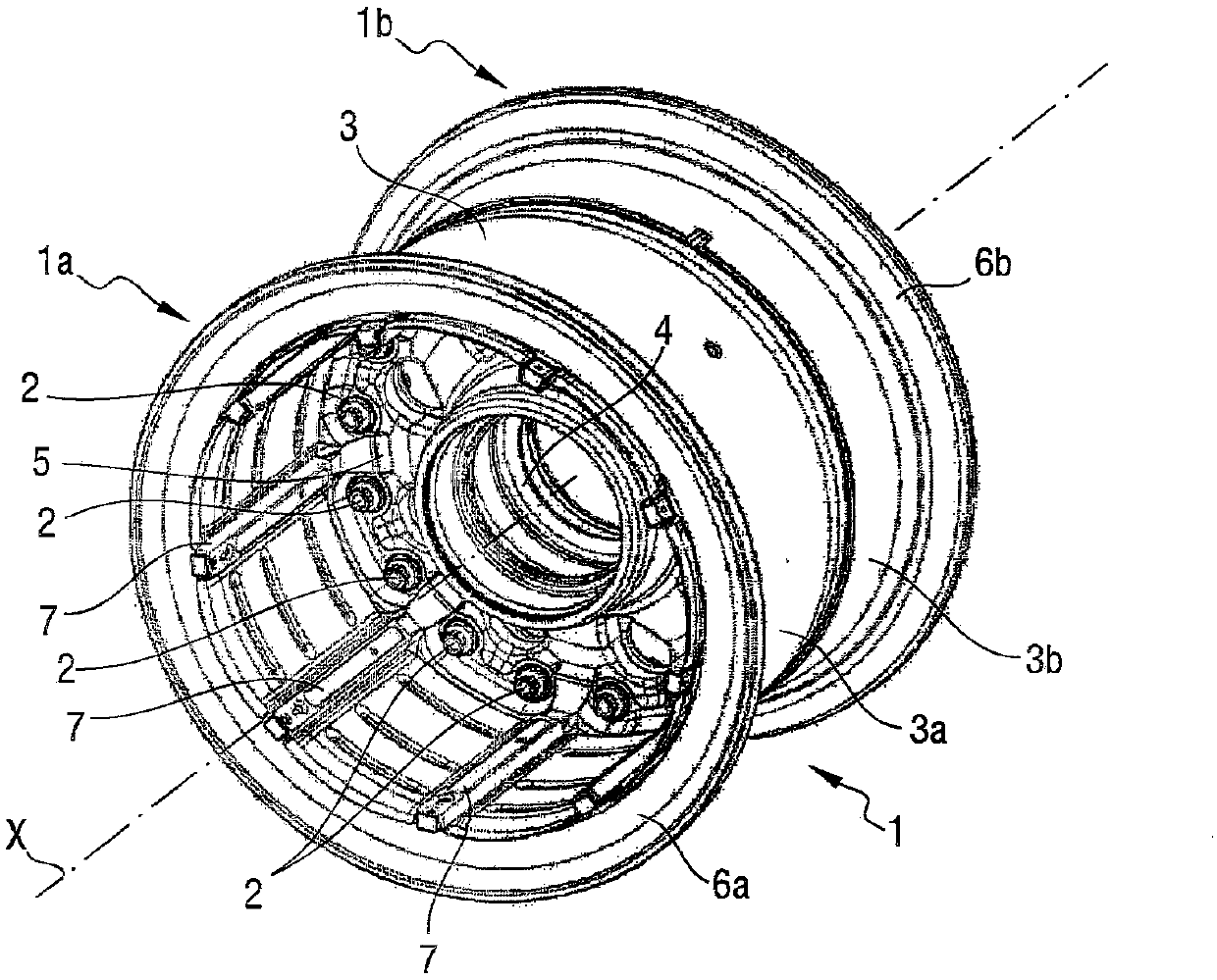
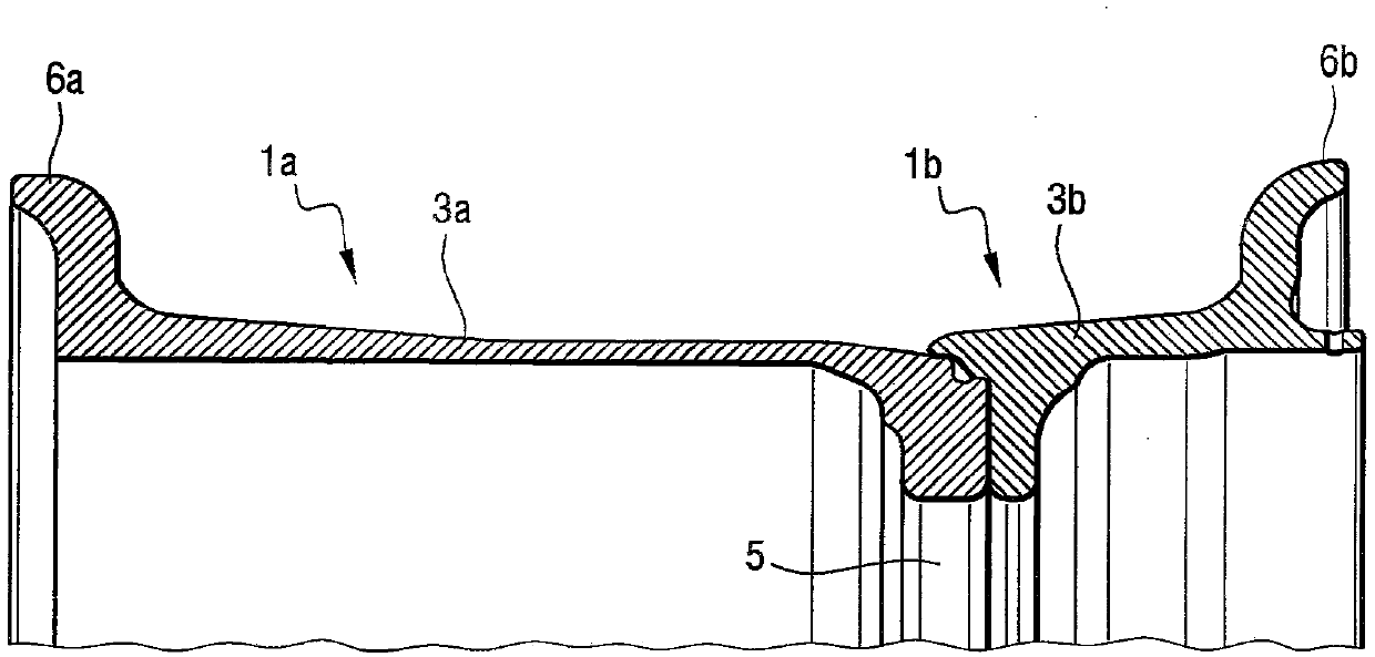
[0015] Figure 1A shows a rim 1 of a conventional brake wheel, consisting of two half-rims 1a and 1b, which are fastened to each other by bolts 2 passing through the disc. The rim 1 has an outer circular portion 3 for receiving a tire (not shown). The rim comprises a hub 4 connected to its outer circular part 3 by a perforated disc 5 . The hub 4 is intended to receive bearings for mounting the wheel on an aircraft landing gear axle such that the wheel rotates about an axis of rotation coinciding with the central axis X of the wheel. The outer circular part 3 comprises two parts 3a and 3b carried by two half-rims 1a and 1b respectively and terminated by respective flanges 6a, 6b. In this example, the half-rim 1a is intended to receive a brake disc and it comprises a ridge 7 extending parallel to the central axis X to receive a corresponding rod engaging in a peripheral notch in the brake disc. As can be seen from FIG. 2A , the profile of the outer circular portion 3 extends su...


PUM


Abstract

The invention provides a rim for a braked aircraft wheel, the rim comprising an outer circular portion (103) terminated at its ends by flanges (106a, 106b) for receiving a tire, the outer circular portion being connected by a wheel disk (105) to a hub (104) for fitting on an undercarriage axle in order to rotate about an axis of rotation coinciding with a central axis (X) of the rim, the rim beingdesigned to receive a tire on the outside of the outer circular portion and a brake on the inside, on one side of the wheel disk. According to the invention, the outer circular portion (103a) on theside of the wheel disk that is to receive a brake presents, in a plane containing the central axis of the wheel, a profile that has two slopes alpha and beta, relative to a direction parallel to the central axis on going from the wheel disk to the corresponding flange, and flaring towards the flange.

Description

technical field [0001] The invention relates to a rim for braking an aircraft wheel. Background technique [0002] It is known that aircraft wheels are mounted on the main landing gear of the aircraft and are designed to cooperate with brakes. Typically, the brake consists of a disc extending inside the rim of the aircraft wheel, the discs comprising stator discs resisting rotation and arranged alternately with rotor discs driven in rotation by the rim of the aircraft wheel via a rod fixed to the rim and engaged in the rotor In the perimeter notch of the plate. Controlled pressure is applied to the set of discs to create friction between the discs facing each other and thereby create a braking torque that slows the rotation of the aircraft wheels. Due to the brakes applied to the wheels of the aircraft, the temperature of the brake disc can increase very significantly. It is important to ensure that the temperature of the rim does not reach a temperature that may be harmf...

Claims


Application Information

Patent Timeline
Patent Type & Authority Applications(China)
IPC IPC(8): B64C25/36B60B19/10B60B21/08
CPCB60B21/023B60B21/026B60B21/04B60Y2200/51B60B25/002B60B2900/513B64C25/36B60B21/02B60Y2200/50B60B21/08
Inventor P·苏布郎特M·阿尔努
Owner SAFRAN LANDING SYSTEMS
Why Eureka
Try Eureka