Wing rail clamp

A wing rail and fixture technology, applied in the field of wing rail fixtures, can solve the problems affecting safe production, product quality and production efficiency, poor end heat treatment quality, and overburning of quenched ends, and achieves light weight and simple structure. , Eliminate the effect of overburning

Pending Publication Date: 2019-05-28
CHINA RAILWAY CONSTR HEAVY IND
View PDF0 Cites 0 Cited by
  • Summary
  • Abstract
  • Description
  • Claims
  • Application Information

AI Technical Summary

Problems solved by technology

Therefore, when clamping, the rail waist at the end of the wing rail cannot be inserted vertically into the guide rail fixture, and it is very difficult to clamp the wing rail into the general 60kg / m rail guide rail fixture
[0004] In addition, there are problems in the heat treatment process of rolled wing rails that affect safety production, product quality and production efficiency. For example, when lifting, because the rail parts are in a tilted state, it is difficult to insert the guide rail clamps clamped by the rail limbs and the rail bottom. , so usually the splint reformed guide rail fixture is used to plug the insulating sheet
The current operation will lead to poor heat treatment quality of the end, and there is a hidden danger of ignition and overburning of the quenched end
At the same time, the finely adjusted wing rails are prone to distortion and deformation when lifted, resulting in changes in the size of the wing rails

Method used


Image

  • Wing rail clamp

Examples


Embodiment Construction

[0021] The present invention will be further described in detail through the accompanying drawings and specific embodiments below, but the protection scope of the present invention will not be limited thereby.

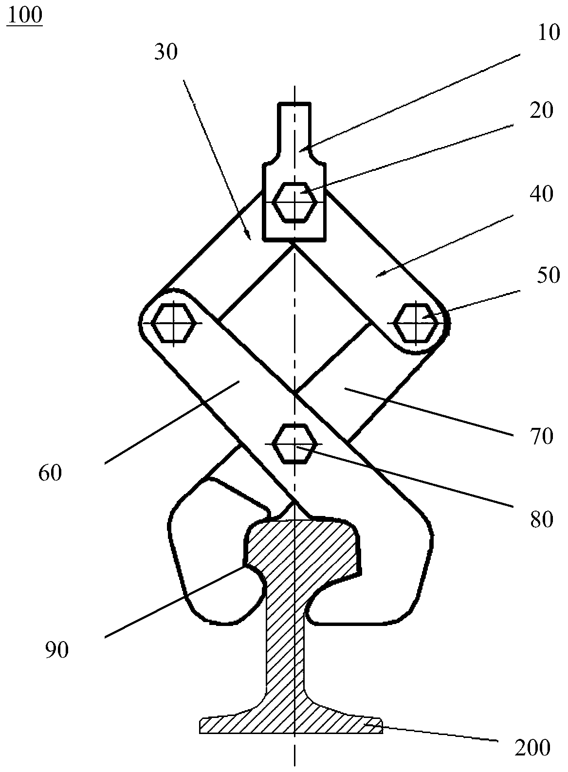
[0022] figure 1 The structure of the wing rail clamp 100 according to the present invention is shown. Such as figure 1 As shown, the wing rail clamp 100 includes lifting lugs 10 , and the lifting lugs 100 are used to connect with a lifting device, so as to lift and control the wing rail clamp 100 . The connection between the wing rail clamp 100 and the lifting device is facilitated by the lifting lug 10, and the operation is simple and easy to control.

[0023] According to the present invention, the wing rail clamp 100 further includes a first movable arm 30 and a second movable arm 40 . Such as figure 1 As shown, the first movable arm 30 and the second movable arm 40 are hinged at the ends through the first hinge shaft 20 . At the same time, the lifting lug 10 i...


PUM


Abstract

The invention provides a wing rail clamp. The wing rail clamp comprises a lifting lug for being connected with a lifting device, a first movable arm, a second movable arm, a first clamping arm and a second clamping arm. The first movable arm and the second movable arm are hinged to the lifting lug through a first hinge shaft. The first clamping arm and the second clamping arm are hinged to the first movable arm and the second movable arm. The first clamping arm and the second clamping arm are hinged through a second hinge shaft to form an intersection. The ends of the first clamping arm and the second clamping arm are configured into hook shapes, a clamping part for clamping a wing rail is formed by the ends of the first clamping arm and the second clamping arm jointly, the opening degreeand the clamping force of the clamping part can be adjusted by lifting the wing rail clamp through the lifting lug, and therefore the wing rail is clamped.

Description

technical field [0001] The invention relates to the technical field of turnout manufacturing industry, in particular to a wing rail clamp. Background technique [0002] With the development of railway technology, wing rails are widely used in frog structures of turnouts. [0003] The wing rail rail itself belongs to the asymmetric cross-section rail, and the finished product after machining is in a tilted state after being hoisted. Therefore, when clamping, the rail waist at the end of the wing rail cannot be vertically inserted into the guide rail fixture, and it is very difficult to clamp the wing rail into the general 60kg / m rail guide rail fixture. [0004] In addition, there are problems in the heat treatment process of rolled wing rails that affect safety production, product quality and production efficiency. For example, when lifting, because the rail parts are in a tilted state, it is difficult to insert the guide rail clamps clamped by the rail limbs and the rail b...

Claims


Application Information

Patent Timeline
Patent Type & Authority Applications(China)
IPC IPC(8): B66C1/30B66C1/64
Inventor 刘飞香刘皓蒋荣国罗震蒋红亮刘志超林志文胡洋
Owner CHINA RAILWAY CONSTR HEAVY IND
Why Eureka
Try Eureka