Novel engineering road paver

A paving machine and engineering technology, applied in the direction of roads, roads, road repairs, etc., can solve the problems of inconvenient crushing and mixing of stone materials, the progress of crushing and mixing, and the inability to carry out stone materials, etc.

Active Publication Date: 2019-05-28
浦江县嘉昱机械有限公司
View PDF8 Cites 2 Cited by
  • Summary
  • Abstract
  • Description
  • Claims
  • Application Information

AI Technical Summary

Problems solved by technology

[0002] For example, the patent number is CN201420720190.X, a paving machine that wraps the whole of the paving machine; the vibration device of the paving machine is composed of a vibrator transmission device, a vibrating plate, a vibrating tube, and a vibration damping device, and is welded on the frame of the machine body. The device and the vibrating device are fixed together; the vibrating plate outputs the vibrating force at the same time to make the paving machine perform the operation of vibrating the slurry. The reducer is connected, and the reducer and the bridge wheel set are fixed on the vibrating plate, and the reducer is driven by the bridge wheel set to provide the deceleration function for the paving machine; the wire rope fixed pulley is connected to the wire rope drum through the wire rope; concrete scraper, concrete The rear scraper is fixed in front of the body frame in the order of front and back. The concrete scraper is used to flatten the concrete piled on the road surface. The concrete rear scraper cooperates with the concrete scraper to control the paving strength of the concrete; the thickness of the pavement The adjusting plate is installed under both sides of the body frame, but the disadvantage of this invention is that the crushing and mixing of stones cannot be carried out while paving the road, and it is inconvenient to carry out crushing and mixing of stones separately

Method used


Image

  • Novel engineering road paver
  • Novel engineering road paver
  • Novel engineering road paver

Examples


specific Embodiment approach 1

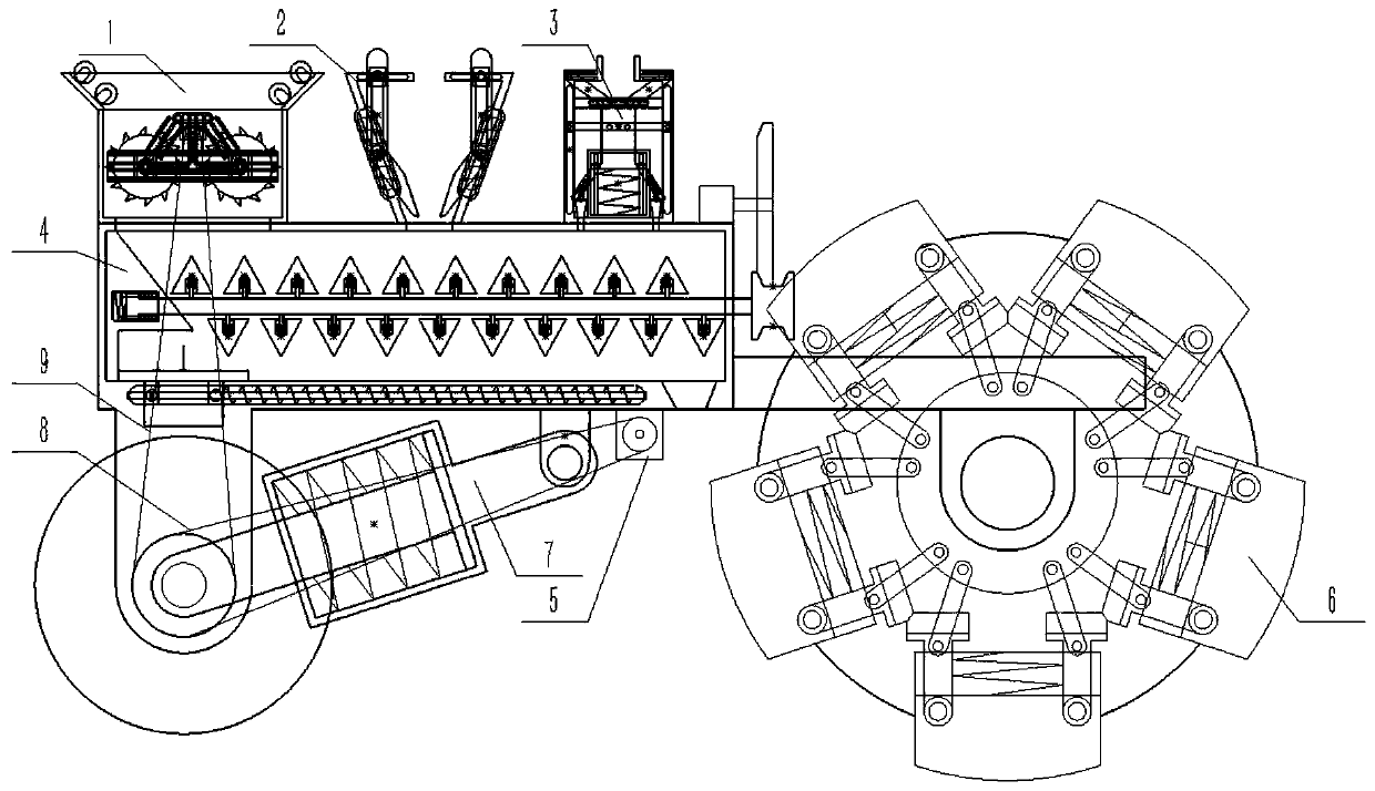
[0040] Combine below Figure 1-22 Description of this embodiment, a new type of engineering paving machine, including a stone crushing wheel 1, a mineral frame 2, a melting liquid device 3, a crushing and mixing device 4, a motor 5, a rolling wheel 6, a shock absorber 7, a synchronous belt 8 and Synchronous belt two 9, the stone crushing wheel 1, the mineral outer frame 2 and the melting liquid device 3 are all fixedly connected to the crushing and mixing device 4, and the stone crushing wheel 1, the mineral outer frame 2 and the melting liquid device 3 are all connected to the crushing and mixing device 4 is connected, the motor 5 is fixedly connected with the pulverizing and mixing device 4, the rolling wheel 6 is rotationally connected with the pulverizing and mixing device 4, the shock absorber 7 is hingedly connected with the pulverizing and mixing device 4, and the timing belt 18 is connected between the pulverizing and mixing device 4 and the motor 5 Between, two synchr...

specific Embodiment approach 2

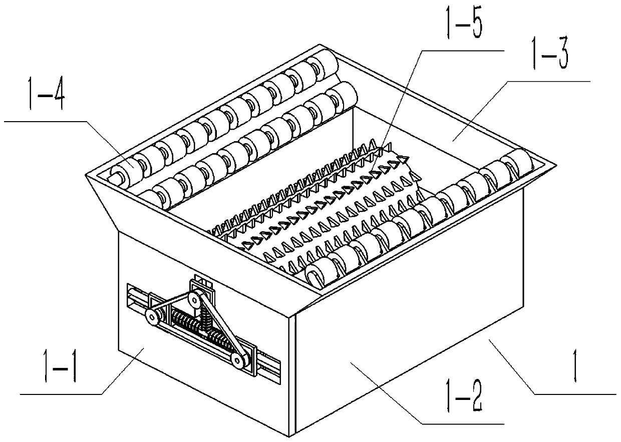
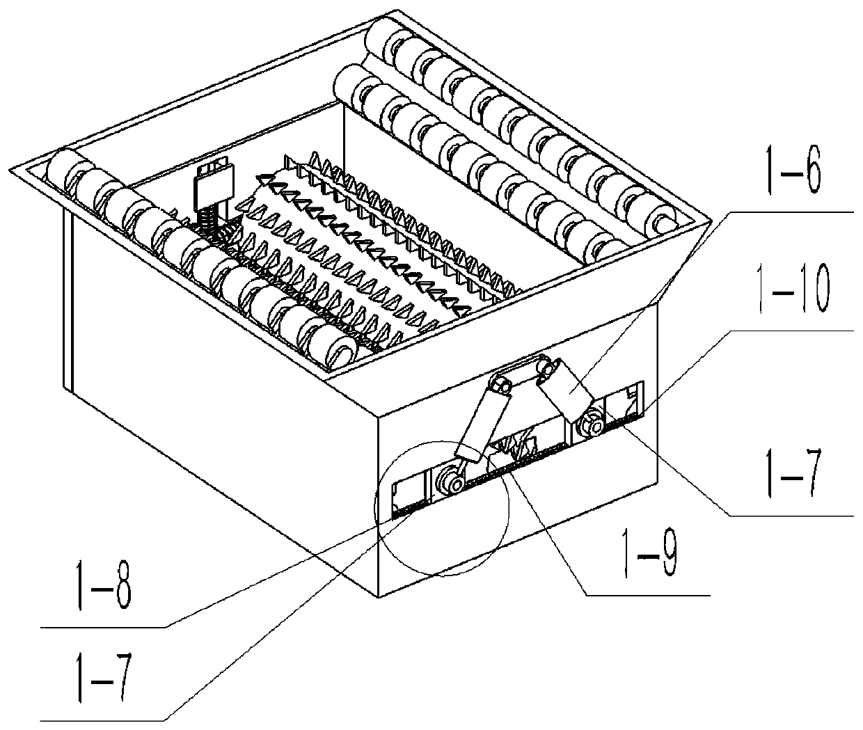
[0041] Combine below Figure 1-22 Describe this embodiment, this embodiment will further explain Embodiment 1. The stone crushing wheel 1 includes a front end frame device 1-1, a main body frame 1-2, an upper side frame 1-3, a rolling stone roller 1-4, Crushing roller 1-5, limit fit body 1-6, two hinged sliders 1-7, two sleeve springs 1-8, sleeve spring 2 1-9, cylindrical slide bar 1-10 and rectangular chute 1-11, the front-end frame device 1-1 includes a front-end vertical plate 1-1-1, a D-shaped sliding rod 1-1-2, a D-shaped chute 1-1-3, and a D-shaped rod sleeve spring 1-1 -4, the upper side sleeve spring 1-1-5, the connecting strip 1-1-6 and three sliding hinged terminals 1-1-7, the D-shaped chute 1-1-3 is arranged on the front vertical plate 1-1- The middle end of 1, the D-shaped sliding rod 1-1-2 is fixedly connected to the inner end of the D-shaped chute 1-1-3, the D-shaped rod sleeve spring 1-1-4 and the upper side sleeve spring 1-1-5 They are all socketed on the D-s...

specific Embodiment approach 3

[0043] Combine below Figure 1-22 Describe this embodiment, this embodiment will further explain Embodiment 1, the mineral outer frame 2 includes a mineral outer frame body 2-1, a material lever 2-2, a material push spring 2-3 and a material outlet 2-4 , the mineral frame body 2-1 includes a mineral frame 2-1-1, two frame side wall sliders 2-1-2, two frame side wall waist grooves 2-1-3 and a hollow cavity 2-1-4, the two outer frame side wall slide bars 2-1-2 are respectively arranged on the side walls of the mineral outer frame 2-1-1 of the body, and the waist grooves 2-1-3 of the two outer frame side walls are respectively On the side wall of the body mineral outer frame 2-1-1, the hollow cavity 2-1-4 is arranged at the inner end of the body mineral outer frame 2-1-1, and the material lever 2-2 includes the material lever Body 2-2-1, material lever slider 2-2-2, material lever slider 2-2-3 and material lever hinged terminal 2-2-4, material lever 2-2-3 and material lever The...


PUM


Abstract

The invention relates to a road paver, in particular to a novel engineering road paver. A stone crushing wheel is arranged to crush stones different in size; a blending liquid device can add a blending liquid automatically when asphalt is mixed; a cleaning terminal is arranged in a crushing and mixing device, so that the device is conveniently cleaned after the asphalt is mixed; a shock absorber is arranged in the device, so that vibration to the body during road pressing can be reduced. The novel engineering road paver comprises the stone crushing wheel, a mineral outer frame, the blending liquid device, the crushing and mixing device, a motor, a grinding wheel, the shock absorber, a synchronous belt I and a synchronous belt II. Two hinge slide blocks can be arranged in a rectangular chute conveniently, two sleeve springs I and II can be connected to the columnar slide bar in a sleeving manner conveniently, and the two hinge slide blocks can be slidably connected to the rectangular chute conveniently. A material push spring can be connected to the slide bar on the side wall of the outer frame conveniently in a sleeving manner, a discharge port can be formed in the lower side of the inner end of the mineral outer frame of the body conveniently, and the inner end of the mineral outer frame of the body can communicate to the discharge port conveniently.

Description

technical field [0001] The invention relates to a paving machine, in particular to a novel engineering paving machine. Background technique [0002] For example, the patent number is CN201420720190.X, a paving machine that wraps the whole of the paving machine; the vibration device of the paving machine is composed of a vibrator transmission device, a vibrating plate, a vibrating tube, and a vibration damping device, and is welded on the frame of the machine body. The device and the vibrating device are fixed together; the vibrating plate outputs the vibrating force at the same time to make the paving machine perform the operation of vibrating the slurry. The reducer is connected, and the reducer and the bridge wheel set are fixed on the vibrating plate, and the reducer is driven by the bridge wheel set to provide the deceleration function for the paving machine; the wire rope fixed pulley is connected to the wire rope drum through the wire rope; concrete scraper, concrete ...

Claims


Application Information

Patent Timeline
Patent Type & Authority Applications(China)
IPC IPC(8): E01C19/48
Inventor 刘志伟
Owner 浦江县嘉昱机械有限公司
Why Eureka
Try Eureka