Sliding vane expander comprising cylinder rotated with rotor

A sliding vane type, expander technology, applied in the field of expanders, can solve the problems of small crescent-shaped chamber volume, limited working flow, low efficiency, etc., and achieves the effects of long service life, avoiding working fluid pollution, and improving efficiency.

Inactive Publication Date: 2019-05-28
SOUTHEAST UNIV
View PDF7 Cites 0 Cited by
  • Summary
  • Abstract
  • Description
  • Claims
  • Application Information

AI Technical Summary

Problems solved by technology

[0003] The synchronous rotary compressor can greatly reduce the relative speed and friction loss between the sliding vane and the cylinder, but it has only one sliding vane, which has low efficiency and large pulsation; another kind of sliding vane compressor in which the cylinder rotates with the rotor is equipped with multiple Sliders, improved pulsation
However, the volume of the crescent-shaped chamber in the tangential structure of the turntable and the cylinder of the above two compressors is small, which limits their working flow

Method used


Image

  • Sliding vane expander comprising cylinder rotated with rotor
  • Sliding vane expander comprising cylinder rotated with rotor

Examples


Embodiment Construction

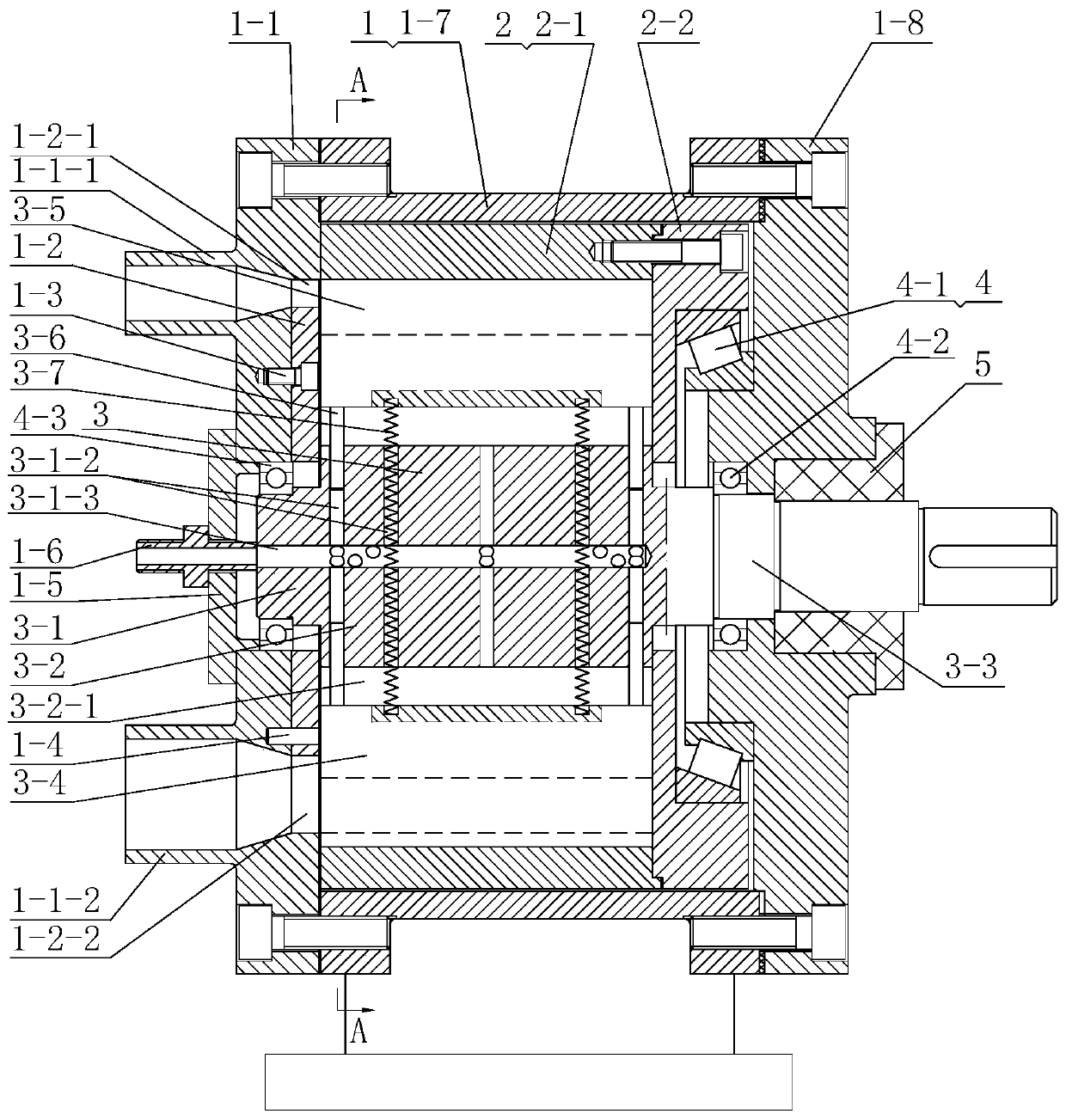
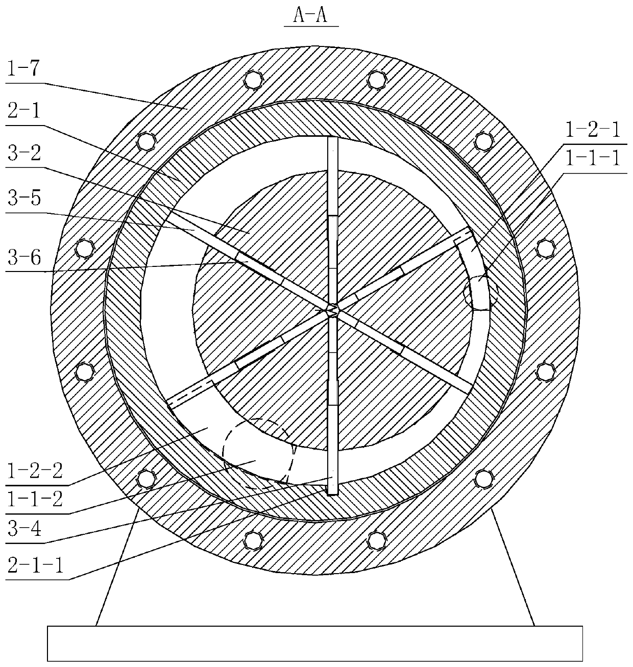
[0021] In order to make the purpose and technical solutions of the embodiments of the present invention more clear, the technical solutions of the embodiments of the present invention will be clearly and completely described below in conjunction with the drawings of the embodiments of the present invention. Apparently, the described embodiments are some, not all, embodiments of the present invention. Based on the described embodiments of the present invention, all other embodiments obtained by persons of ordinary skill in the art without creative efforts shall fall within the protection scope of the present invention.

[0022] Those skilled in the art can understand that, unless otherwise defined, all terms (including technical and scientific terms) used herein have the same meaning as commonly understood by one of ordinary skill in the art to which this invention belongs. It should also be understood that terms such as those defined in commonly used dictionaries should be und...


PUM


Abstract

The invention discloses a sliding vane expander comprising a cylinder rotated with a rotor. The sliding vane expander comprises a casing, a moving cylinder, the rotor, a bearing pack and mechanical seals; a barrel of the casing is internally provided with the moving cylinder coaxially, and the cylinder is internally provided with the rotor eccentrically, but the outer diameter of a rotating disk is kept for a certain distance with the wall of the cylinder; 6-12 (an even number of) axial rectangular grooves are distributed in the rotating disk uniformly, and sliding vanes are arranged in the grooves; a wide sliding vane is embedded into a trapezoid groove of the cylinder for driving the moving cylinder to rotate synchronously; a left end plate of the casing is provided with an air inlet andan air outlet, and communicates with an airfoil inlet gap and an outlet gap in a guide disk through a transition chamber; and both the inlet gap and the outlet gap communicate with a chamber betweenthe cylinder and the rotating disk smoothly. The relative speed difference between the moving cylinder and the sliding vanes is lower, and the frictional loss is less; and the expander has the advantages of high efficiency, large flow, the simple structure and the like.

Description

technical field [0001] The invention relates to an expander, in particular to a sliding vane expander with a rotating cylinder. Background technique [0002] Organic Rankine cycle ORC, Kalina cycle, CO in low-grade energy utilization 2 Small and medium-sized expanders are required for working fluid power cycles and full-flow steam-water mixture power generation cycles. In some special occasions, such as supercritical water gasification coal technology and gas-steam mixed working medium cycle technology for existing power plants CO 2 The transformation of full capture also requires a pre-expander to improve system efficiency, and its application conditions are high parameters, low pressure ratio, and small volume flow. However, the structure of the turbo expander is relatively complicated and it is difficult to manufacture. Modern turbine blades designed using ternary flow theory are the jewel in the crown of the machinery manufacturing industry. While bringing efficiency ...

Claims


Application Information

Patent Timeline
IPC IPC(8): F01C1/344F01C21/08F01C21/10F01C21/06
Inventor 陈亚平梅贤智蒋芸慧吴嘉峰
Owner SOUTHEAST UNIV
Why Eureka
Try Eureka