
Wedge-shaped flow sensor with balance structure

A flow sensor and balanced structure technology, which is applied in the field of flow sensors, can solve the problems of excessive machining fit size, no grinding of welds, time-consuming, etc., to achieve the effect of solving zero drift and ensuring measurement accuracy

Active Publication Date: 2019-05-28
江苏华海测控技术有限公司
View PDF8 Cites 0 Cited by
  • Summary
  • Abstract
  • Description
  • Claims
  • Application Information

AI Technical Summary

Problems solved by technology

[0003] The current wedge-shaped flow sensor has the following disadvantages: first, the welding of the pressure port is easy to leak, and the welding of the wedge block is easy to leak; at the same time, after welding, the welding is not allowed to be polished, which affects the appearance of the product; second, welding is difficult, time-consuming and expensive. The third is that the processing technology of the parts is cumbersome, and there are too many machining matching dimensions; the fourth is that after the zero point drift occurs after the installation and installation of the double-flange pressure transmitter on site, the differential pressure transmitter needs to be adjusted

Method used


Image

  • Wedge-shaped flow sensor with balance structure
  • Wedge-shaped flow sensor with balance structure
  • Wedge-shaped flow sensor with balance structure

Examples


Embodiment 1

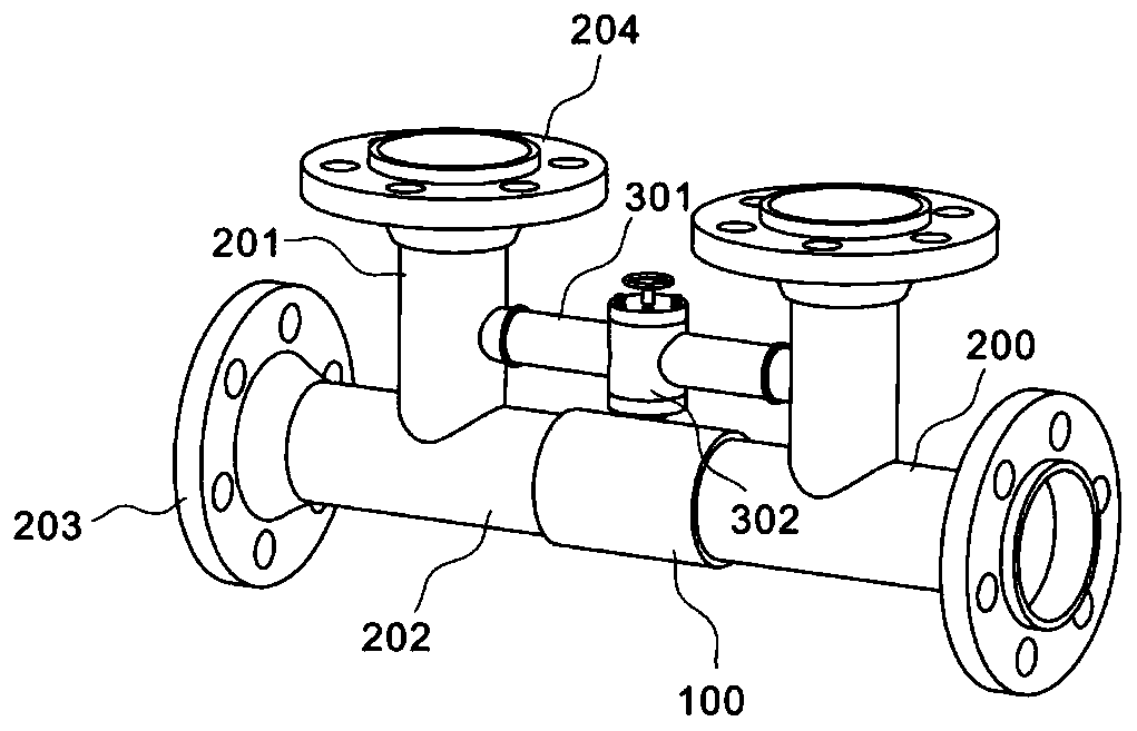
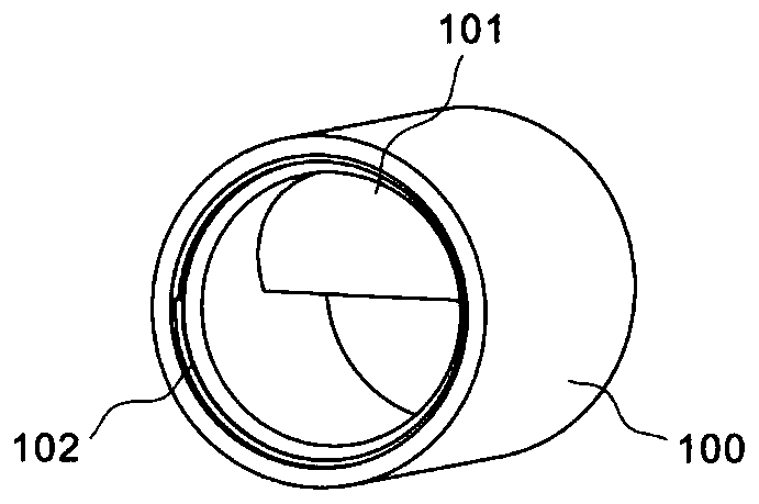
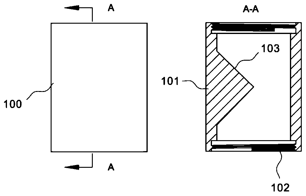
[0036] refer to Figure 1~3 In order to be able to solve the existing wedge-shaped flow sensor, one is easy to leak at the welding part of the pressure taking port, and the welding part of the wedge block is easy to leak; second, after welding, the welding part is not allowed to be polished, which affects the appearance of the product; third, it is difficult to weld , time-consuming and easy to deform after welding, and the problem that the differential pressure transmitter needs to be adjusted after the zero point drift occurs after the installation and installation of the double-flange pressure transmitter on site. In this embodiment, a wedge-shaped flow sensor with a balanced structure is proposed, including a wedge-shaped pipe 100, a tee pipe 200, and a balance unit 300. The wedge-shaped pipe 100 is a connecting pipe with a built-in wedge block 101; the tee is also called a pipe fitting tee or three-way Through pipe fittings, tee joints, etc., which are mainly used to chan...

Embodiment 2

[0040] refer to Figure 4~5 For illustration, in the first embodiment, the balance unit 300 needs to be connected and installed with the pressure-taking pipes 201 at both ends during use. It is determined immediately, so during the process of installing the balance unit 300 between the two pressure-taking pipelines 201, for a fixed-length balance unit 300, if the length of the balance unit 300 is less than the distance between the two pressure-taking pipelines 201, the balance unit 300 When put in, there is a distance gap at the butt joint of the two pipes, so the extrusion force between them will also be insufficient due to the existence of the gap, which will affect the sealing performance of the pipe butt joint. However, if the length of the balance unit 300 is increased, that is, the length of the balance guide tubes 301 at both ends, that is greater than the distance between the two pressure-taking pipes 201, the extrusion between the balance unit 300 and the pressure-tak...

Embodiment 3

[0044] refer to Figure 6-10 In this embodiment, the telescopic movement between the mounting part 401 and the rotating part 402 can be adjusted so as to adapt to the balance unit 300 of different lengths, which can make the balance units 300 of different lengths have better sealing performance. Therefore, the difference with the second embodiment is that: the installation part 401 also includes a fixed extension part 401c, a locking part 401d, a telescopic part 401e, an elastic part 401f and a limiting groove 401g; The part 402 also includes a spring column 402d, a limit shaft 402e, a swivel 402f, a toggle tooth 402g and a handle 402h. More specifically, the split ring 401a in this embodiment is a symmetrical semi-circular body connected by two rotating shafts. When the split ring 401a is opened, the flange parts at both ends of the balance guide tube 301 are fitted into the stopper groove 401g and limited by engagement. It should be noted that the relative rotation between ...


PUM


Abstract

The invention discloses a wedge-shaped flow sensor with a balance structure. The wedge-shaped flow sensor comprises a wedge-shaped pipeline, three-way pipelines and a balance unit, wherein a wedge-shaped block is arranged in the wedge-shaped pipeline; the three-way pipelines are arranged at the two ends of the wedge-shaped pipeline and communicated with the wedge-shaped pipeline, and pressure obtaining pipelines are arranged above the three-way pipelines; the two ends of the balance unit are communicated with the pressure obtaining pipelines. The wedge-shaped flow sensor has the advantages that the wedge-shaped block is welded in the wedge-shaped pipeline, and through the internal welding, welding deformation and leakage are avoided easily in a wedge-shaped flow sensor made through a traditional technology; a balance leading pipe is connected between two connecting pressure obtaining standard flanges, a balance valve is installed on the balance leading pipe, the problem of zero drift after a differential pressure transmitter is installed is solved better, and the measuring precision of the wedge-shaped flow sensor is guaranteed better.

Description

technical field [0001] The invention relates to the technical field of flow sensors, in particular to a wedge-shaped flow sensor with a balance structure. Background technique [0002] In recent years, the working principle of the wedge-shaped flow sensor is the same as that of other differential pressure instruments. The wedge-shaped flow sensor is also based on Bernoulli's formula, using the law of energy conservation in the flow process of the fluid, that is, the sum of kinetic energy and static pressure energy remains unchanged, so that The flow is measured by the principle of differential pressure generated when the fluid passes through the wedge-shaped block that acts as a throttling. When the fluid flows through the wedge-shaped throttling block, the flow area decreases, the flow velocity increases, and the static pressure decreases, resulting in a static pressure difference. Since the square root of the pressure difference is proportional to the flow rate, the flow ...

Claims


Application Information

Patent Timeline
Patent Type & Authority Applications(China)
IPC IPC(8): G01F1/36G01F1/40
Inventor 徐锋
Owner 江苏华海测控技术有限公司
Learn More