Control structure and method for preventing welding deformation of upwarp type top beam

A welding deformation and structure control technology, which is applied in welding equipment, auxiliary welding equipment, welding/cutting auxiliary equipment, etc., can solve the problem that the effect of the upturned top beam is not obvious, and achieve the effect of solving welding deformation and controlling welding deformation

Pending Publication Date: 2020-10-16
CHINA COAL BEIJING COAL MINING MACHINERY
View PDF0 Cites 2 Cited by
  • Summary
  • Abstract
  • Description
  • Claims
  • Application Information

AI Technical Summary

Problems solved by technology

[0010] The above scheme can reduce the welding deformation to a certain extent, but for the upturned roof beam due to the particu

Method used


Image

  • Control structure and method for preventing welding deformation of upwarp type top beam
  • Control structure and method for preventing welding deformation of upwarp type top beam
  • Control structure and method for preventing welding deformation of upwarp type top beam

Examples


specific Embodiment approach

[0023] The preferred specific implementation method of the upturned top beam prevention welding deformation control structure of the present invention is:

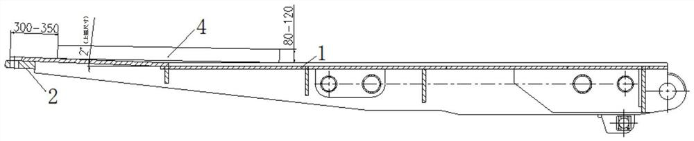
[0024] The top beam includes a top plate, the front end of the top plate is welded with a tongue plate, including clips for assembly, before welding, the top plate and the tongue plate are clamped with the clips, and the tongue plate is equipped with a welding mechanism for welding with the top plate. Anti-deformation structures with opposite deformation directions and similar magnitudes.

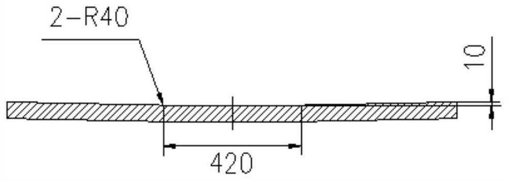
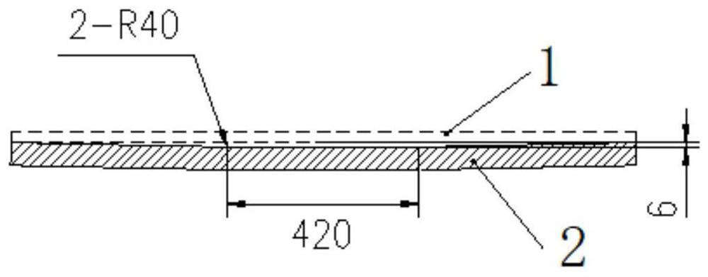
[0025] Before welding, two strip-shaped fixing plates are longitudinally fixed on the back of the top plate, and pad iron is added between the top plate and the fixing plate, and the thickness of the pad iron is the deformation amount of the top plate after welding.

[0026] The method for controlling welding deformation of the above-mentioned upturned top beam preventing welding deformation control structure includes:

[0027] Accordi...

specific Embodiment

[0031] The anti-deformation method of the tongue plate is shown in Figure 1. According to the structural characteristics of the top beam parts and the analysis of the deformation after welding, a deformation of the tongue plate is opposite to the welding deformation direction and similar in size in advance, and the clips are used when the top beam parts are assembled once. The fixed tongue plate is used to offset the deformation of the structural parts after welding and prevent bending deformation and angular deformation.

[0032] The roof fixture fixing method is shown in Figure 2. For a structure with a thin roof beam and a large upwarp, two long strips are fixed at an appropriate position behind the roof. Add iron pads between the fixed plates to pre-deform the top plate, and weld temporary spot welds around the fixed plates to reduce the wave deformation after welding. This welding fixture can also be used to increase the rigidity and restraint of the structure.

[0033] ...


PUM


Abstract

The invention discloses a control structure and method for preventing welding deformation of an upwarp type top beam. The top beam comprises a top plate, a tongue plate welded to the front end of thetop plate and a clamp for assembly, the top plate and the tongue plate are clamped through the clamp before welding, and the tongue plate is provided with a reverse deformation structure which is opposite in the welding deformation direction of the top plate and similar in size. Before welding, two long-strip-shaped fixed plates are longitudinally fixed to the back face of the top plate, sizing blocks are added between the top plate and the fixed plates, and the thickness of the sizing blocks is the deformation amount of the welded top plate. The purpose of controlling welding deformation is achieved by bending a weldment in the direction opposite to the welding deformation in advance through reverse deformation and a clamp fixing method and increasing the rigidity and constraint of a component. The problem of welding deformation of the front end of the upwarp type top beam thin top plate structure is solved.

Description

technical field [0001] The invention relates to a coal mine hydraulic support welding technology, in particular to an upturned top beam preventing welding deformation control structure and method. Background technique [0002] In the coal mine hydraulic support products, the structural parts account for 60%-70% of the total support, and the key process in the structural parts is welding. The quality of the welding process directly affects the overall quality of the product. In welding production, controlling and eliminating welding deformation is one of the most important and difficult points. Due to the high concentration of welding heat sources during welding, the parts of the weldment are heated unevenly, resulting in stress and deformation. If the stress exceeds the yield strength of the material, plastic deformation will occur, and the deformation and residual stress will appear in the structural part after cooling. If the deformation of the structural parts after wel...

Claims


Application Information

Patent Timeline
IPC IPC(8): B23K37/00B23K37/04
CPCB23K37/00B23K37/0426
Inventor 付燕利刘蕴熙
Owner CHINA COAL BEIJING COAL MINING MACHINERY
Why Eureka
Try Eureka