
Aviation obstruction beacon control system based on radar technology and method thereof

A technology of aviation obstruction lights and radar, which is applied in radio wave measurement system, radio wave reflection/re-radiation, utilization of re-radiation, etc., can solve problems affecting human and animal rest, reduce service life, consume large energy, etc., to achieve Restoring the natural ecological environment, improving the service life and reducing the opening time

Pending Publication Date: 2019-05-28
安徽瞭望科技有限公司
View PDF0 Cites 0 Cited by
  • Summary
  • Abstract
  • Description
  • Claims
  • Application Information

AI Technical Summary

Problems solved by technology

[0004] The above-mentioned working environments are basically set up near residential areas. Considering the difference between light pollution and general-purpose lighting, aviation obstruction lights generally do not use constant lighting. In the prior art, flashing methods are often used, but compared to the elapsed time of the aircraft, The overall lighting time of aviation obstruction lights is long, and there are still the following disadvantages: 1. A large number of high-intensity aviation obstruction lights are lit at night, causing light pollution, illuminating the sky, destroying the dark natural environment, and affecting the rest of humans and animals , has been banned in Europe and the United States; 2. High-intensity aviation obstruction lights have high power and consume a lot of energy; 3. Long-term flashing working mode is likely to cause obstruction lights to malfunction and reduce their service life

Method used


Image

  • Aviation obstruction beacon control system based on radar technology and method thereof

Examples


Embodiment Construction

[0026] Specific embodiments of the present invention will be described in detail below in conjunction with the accompanying drawings. It should be understood that the specific embodiments described here are only used to illustrate and explain the present invention, and are not intended to limit the present invention.

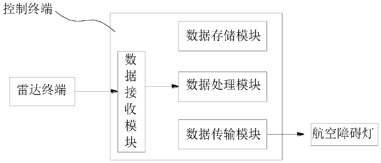
[0027] An aviation obstruction light control system based on radar technology, including a control terminal, a radar terminal and several aviation obstruction lights;

[0028] The control terminal includes a data receiving module, a data processing module, a data transmission module and a data storage module, the radar terminal communicates with the control terminal, and the aviation obstruction light communicates with the control terminal through Ethernet;

[0029] The radar terminal is used for monitoring and collecting position information of low-altitude aircraft;

[0030] The data storage module is used to pre-store marked building location information;

...


PUM


Abstract

The invention discloses an aviation obstruction beacon control system based on a radar technology and a method thereof. An active phased array radar monitors aircrafts in low-altitude airspace where large buildings and single building groups are located, calculates the distances between the low-altitude aircrafts and labeled buildings through a control terminal by utilizing the aircraft position information and the labeled building position information provided by the radar, judges the distances between the low-altitude aircrafts and the labeled buildings, and controls turning-on of aviation obstruction beacons. The turning-on time of the aviation obstruction beacons is greatly reduced, and the lighting time of the aviation obstruction light is reduced by 95%-98%, the light pollution is reduced, the energy consumption is reduced, the carbon emission is reduced, and the service life of the aviation obstruction beacons is prolonged.

Description

technical field [0001] The invention relates to the technical field of radar electronics, in particular to an aviation obstruction light control system based on radar technology and a method thereof. Background technique [0002] With the in-depth development of military-civilian integration, making full use of low-altitude resources has become a social consensus. The country will gradually open up low-altitude airspace, and low-altitude aircraft such as helicopters, airships, and drones will be widely used, but tall buildings are harmful to low-altitude aircraft flying at night. major safety hazard. The current solution is to install aviation obstruction lights on the top of the building, and when the visibility is low, the aviation obstruction lights will light up to guide flying objects to avoid. [0003] Aviation obstruction light (AviaT1ion ObsT1rucT1ion lighT1), also known as navigation aid lighting equipment, is a special lamp for marking obstacles, belonging to the ...

Claims


Application Information

Patent Timeline
Patent Type & Authority Applications(China)
IPC IPC(8): G01S13/93
Inventor 刘联节
Owner 安徽瞭望科技有限公司
Learn More