An Optical Transmitter Box Convenient for Expansion and Retrofit

A technology of optical communication box and box, which is applied in the field of communication, can solve problems such as inconvenient service opening, affecting actual use, affecting line transformation, etc., and achieves good heat insulation effect, convenient maintenance and operation, and convenient post-maintenance effects

Active Publication Date: 2021-01-29
杭州昱华科技有限公司
View PDF11 Cites 0 Cited by
  • Summary
  • Abstract
  • Description
  • Claims
  • Application Information

AI Technical Summary

Problems solved by technology

[0003] In the process of using the existing optical communication box, due to the need to connect several optical fibers inside, it is easy to cause the optical fibers to be entangled with each other, and it is impossible to distinguish and classify them well. This will cause huge troubles and seriously affect the later maintenance and transformation. Line reconstruction; at the same time, unopened business optical fibers cannot be temporarily parked and protected in the optical communication box, which is not convenient for a clear judgment on the opening of the service; at the same time, the internal volume of the existing optical communication box is fixed, which is often It is necessary to expand and transform the optical communication box, and it is necessary to add more fusion devices inside. In this way, it is necessary to install multiple optical communication boxes or replace large-volume optical communication boxes for use, resulting in a waste of resources, and expansion and transformation require One end of the optical fiber in this area will be deactivated for a period of time, which will affect the actual usage

Method used


Image

  • An Optical Transmitter Box Convenient for Expansion and Retrofit
  • An Optical Transmitter Box Convenient for Expansion and Retrofit
  • An Optical Transmitter Box Convenient for Expansion and Retrofit

Examples


Embodiment Construction

[0032] The technical solutions of the present invention will be clearly and completely described below in conjunction with the embodiments. Apparently, the described embodiments are only some of the embodiments of the present invention, not all of them. Based on the embodiments of the present invention, all other embodiments obtained by persons of ordinary skill in the art without creative efforts fall within the protection scope of the present invention.

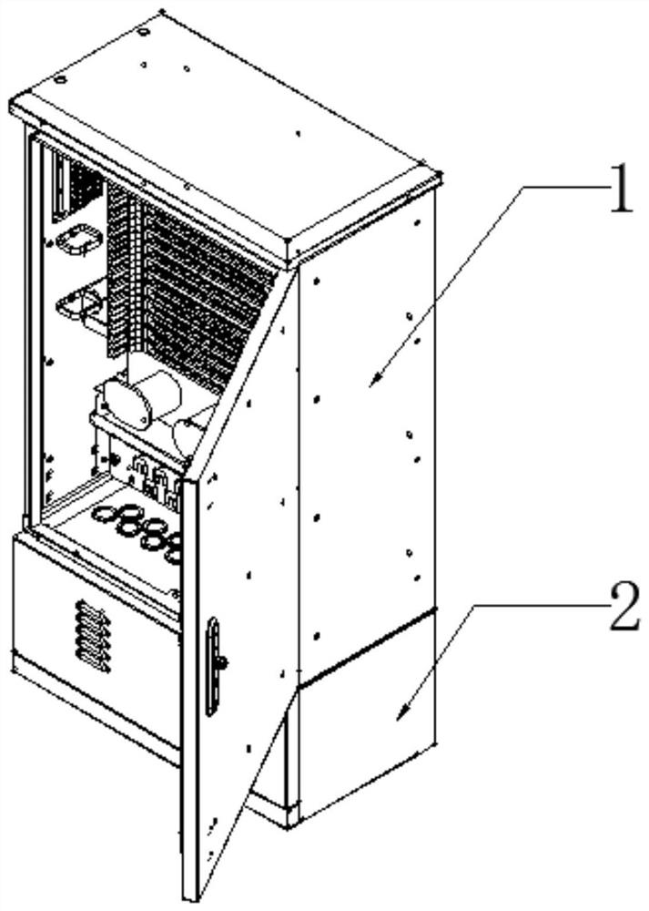
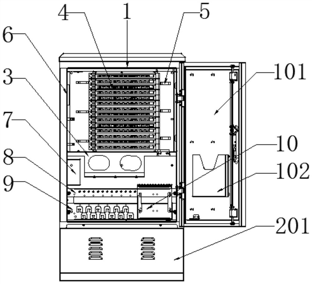
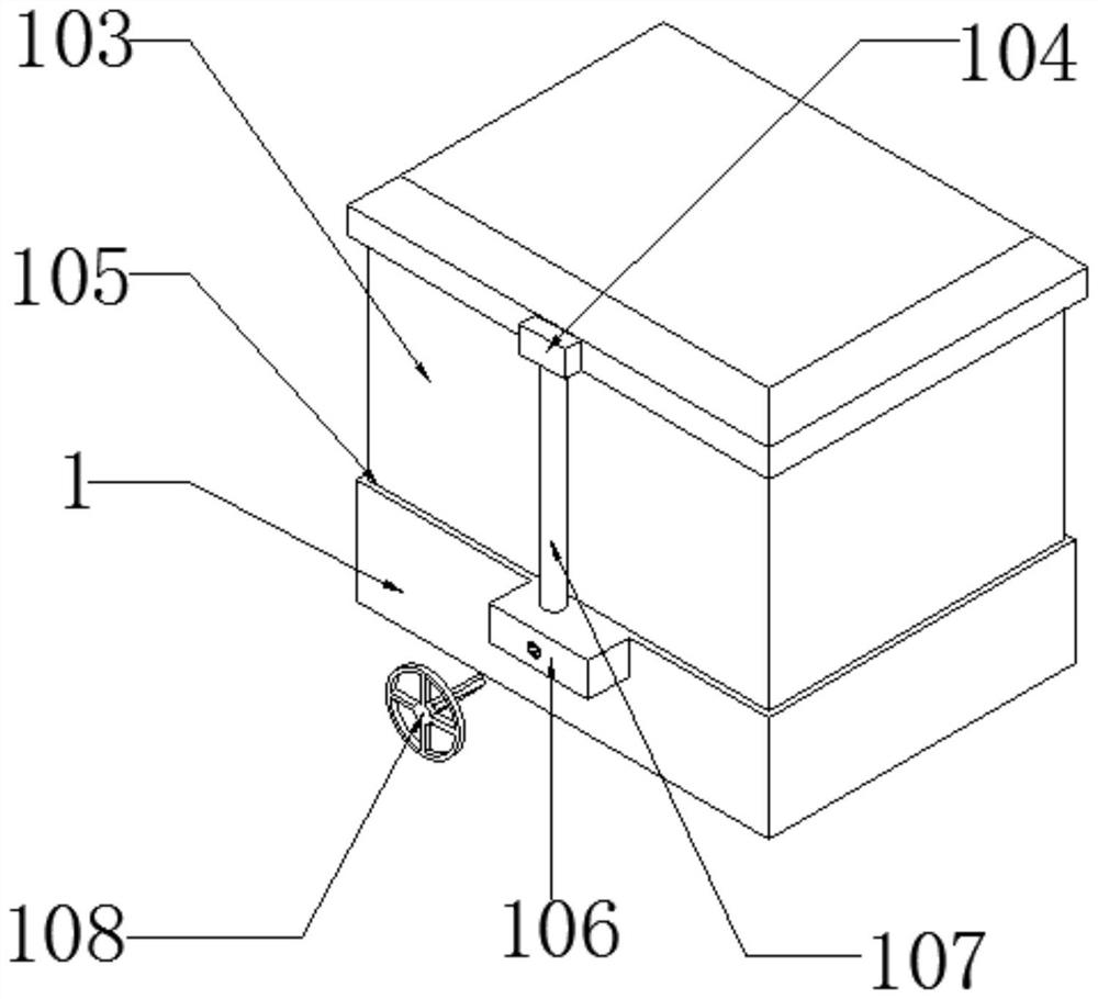
[0033] see Figure 1-8 As shown, an optical communication box that is convenient for capacity expansion and transformation includes a first box body 1, a base 2, a stand 3, a 12-core fusion-matched integrated tray 4, a wire ring 5, a parking device bracket 6, and an optical sub-frame 7 , the first optical cable fixing beam 8, the second optical cable fixing beam 9, the direct melting frame 10, the bottom plate 11, the protective coil 12, the mooring device 13, the optical cable fixing lug 14, the fiber winding tube 15, the ...


PUM


Abstract

The invention discloses an optical communication box which is convenient for capacity expansion and reconstruction, comprising a first box body, a base, a stand, a 12-core melting and matching integrated tray, optical cable fixing lugs, a fiber winding tube, a fiber winding tube cover plate, and an optical cable Steel wire fastening seat, perforation, fastening bolt, chute, installation box, threaded rod, runner, sleeve, slave helical gear, main helical gear, rotating shaft and base door, one side of the first box moves through a hinge A box door is installed, a recording box is installed inside the box door, and a chute is provided on the top of the first box body; the present invention can classify and fix the optical fibers through multiple mechanisms, which is convenient for later maintenance, statistics and transformation; at the same time, through There are multiple mooring devices designed on the structure of the mooring device bracket, which is convenient for the temporary parking and protection of unopened business optical fibers, and at the same time clearly judges the opening of the service; at the same time, the internal volume is expanded by stretching the first box and the second box, which is fast and convenient The completion of the expansion transformation is convenient for practical application.

Description

technical field [0001] The invention relates to the communication field, in particular to an optical communication box which is convenient for capacity expansion and reconstruction. Background technique [0002] The optical cable transfer box, also known as the street cabinet, is usually placed on the main optical cable for branching the optical cable. It is a passive device and has similar functions to the original copper cable transfer box. After passing through the optical cable transfer box, it is divided into several small logarithmic optical cables in different directions. Of course, this function can also be realized by the optical cable splice box, but the difference is that the optical cable transfer box can realize the jumping of optical cables, and can also be used for testing and Maintenance, optical transfer box OCC is mainly suitable for optical transfer points in optical transmission networks and access networks. The box is made of high-quality stainless steel...

Claims


Application Information

Patent Timeline
Patent Type & Authority Patents(China)
IPC IPC(8): G02B6/44
Inventor 羊桃勇朱廷顺张银华裘艳琴
Owner 杭州昱华科技有限公司
Why Eureka
Try Eureka