
Demodulation reference signal sending method, demodulation reference signal receiving method, base station and user equipment

A technology for demodulating reference signals and user equipment, which is applied in wireless communication, baseband system components, and multiple use of transmission paths, and can solve problems such as inability to guarantee channel estimation performance.

Active Publication Date: 2019-05-28
SHENZHEN TRANSSION HLDG CO LTD
View PDF5 Cites 4 Cited by
  • Summary
  • Abstract
  • Description
  • Claims
  • Application Information

AI Technical Summary

Problems solved by technology

[0005] In view of this, the embodiments of the present invention provide a method for sending and receiving a demodulation reference signal, a base station, and a user equipment, so as to solve the problem that the channel estimation performance cannot be guaranteed when scheduling based on mini-slots

Method used


Image

  • Demodulation reference signal sending method, demodulation reference signal receiving method, base station and user equipment
  • Demodulation reference signal sending method, demodulation reference signal receiving method, base station and user equipment
  • Demodulation reference signal sending method, demodulation reference signal receiving method, base station and user equipment

Examples


Embodiment Construction

[0036] The following will clearly and completely describe the technical solutions in the embodiments of the present invention with reference to the accompanying drawings in the embodiments of the present invention. Obviously, the described embodiments are some of the embodiments of the present invention, but not all of them. Based on the embodiments of the present invention, all other embodiments obtained by persons of ordinary skill in the art without making creative efforts belong to the protection scope of the present invention.

[0037] It should be understood that when used in this specification and the appended claims, the terms "comprising" and "comprises" indicate the presence of described features, integers, steps, operations, elements and / or components, but do not exclude one or Presence or addition of multiple other features, integers, steps, operations, elements, components and / or collections thereof.

[0038] It should also be understood that the terminology used ...


PUM


Abstract

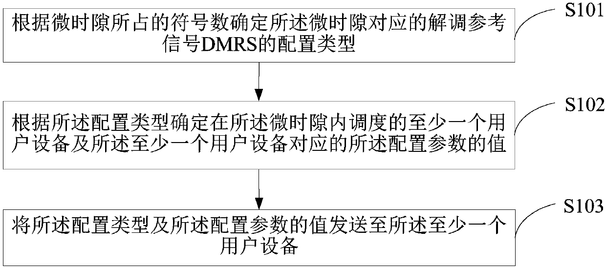
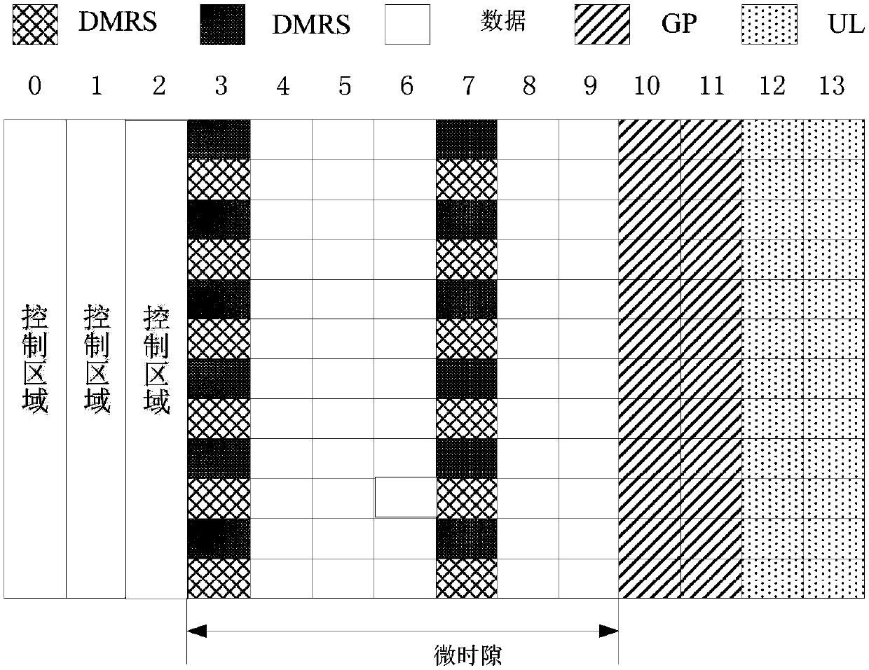
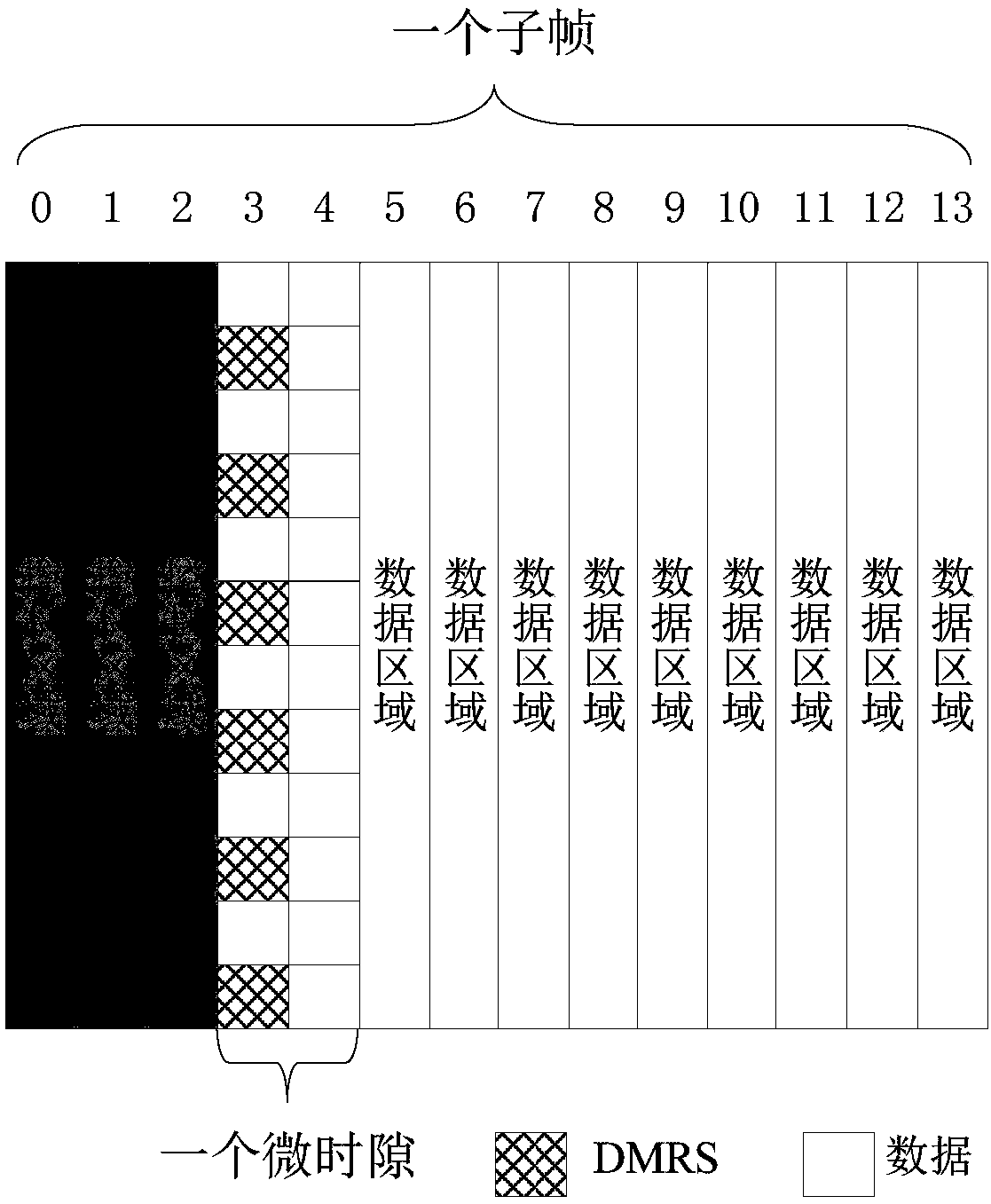
The embodiment of the invention discloses a demodulation reference signal sending and receiving method, a base station and user equipment. The sending method comprises the following steps: determiningthe configuration type of a demodulation reference signal DMRS corresponding to a micro time slot according to the number of symbols occupied by the micro time slot; wherein the configuration parameters corresponding to the configuration types comprise at least one of comb teeth, cyclic shift of the DMRS and symbols occupied by the DMRS, and the number of at least one configuration parameter in different configuration types is different; determining at least one user equipment scheduled in the micro time slot and the value of the configuration parameter corresponding to the at least one userequipment according to the configuration type; And sending the configuration type and the value of the configuration parameter to the at least one user equipment. In the embodiment of the invention, the configuration type of the corresponding DMRS is determined according to the number of symbols occupied by the micro time slot, so that the real-time performance of performing channel estimation through the DMRS is ensured, and the channel estimation performance is ensured.

Description

technical field [0001] The present invention relates to the field of communication technology, in particular to a method for sending and receiving a demodulation reference signal, a base station, and user equipment. Background technique [0002] In the Long Term Evolution (LTE) system, downlink pilots include Cell Reference Signal (Cell Reference Signal, CRS), demodulation reference signal (Demodulation Reference Signal, DMRS) for user demodulation and channel state information Measured Channel State Reference Signal (CSI-RS). In order to reduce unnecessary pilot overhead, in the fifth generation (5th-Generation, 5G) mobile communication system, the CRS is deleted, and the DMRS and CSI-RS are enhanced. For example, a user-level DMRS is set for both the Physical Downlink Control Channel (PDCCH) and the Physical Downlink Shared Channel (PDSCH), so as to improve the performance of shaped reception, and use CSI-RS for the beam Measurements, these functional changes bring corre...

Claims


Application Information

Patent Timeline
IPC IPC(8): H04L5/00H04W72/04H04L25/02
Inventor 王三新
Owner SHENZHEN TRANSSION HLDG CO LTD
Learn More