Mechanical structure of high-frequency electric focusing ion accelerating device and assembling method thereof
A technology of mechanical structure and focusing ions, applied in electrical components, accelerators, etc., can solve the problems of assembly difficulty, cavity assembly failure, and high requirements for assembly accuracy of the entire cavity, to ensure structural stability and alignment adjustment, and reduce assembly difficulty. , to ensure the effect of assembly accuracy
- Summary
- Abstract
- Description
- Claims
- Application Information
AI Technical Summary
Problems solved by technology
Method used
Image
Examples
Embodiment 1
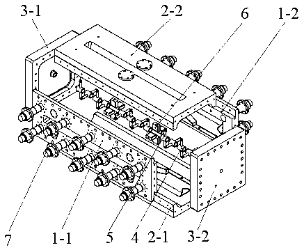
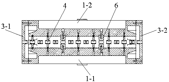
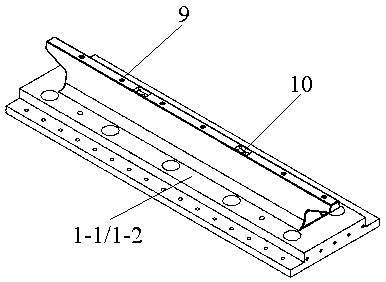
[0039] refer to Figure 1~6 , Embodiment 1 of the present invention provides a mechanical structure of a high-frequency electric focusing ion accelerator, which mainly includes two identical left horizontal single wings 1-1 and right horizontal single wing 1-2 that constitute a high-frequency cavity , two identical upper vertical single wings 2-2 and lower vertical single wings 2-1 and the same front end cover 3-1 and rear end cover 3-2; and, alternately arranged on the central axis of the high frequency cavity There are drift tube assemblies and RF quadrupole field sections.
[0040] Wherein, the above-mentioned drift tube assembly includes a drift tube 4 and two drift tube support rods 5 arranged symmetrically in its radial direction. On the two oppositely arranged single wings (the end connected to the drift tube 4 is the inner end); the drift tube components are distributed horizontally and vertically alternately. The drift tube support rod 5 is fastened on the single wi...
Embodiment 2
[0044] Based on the mechanical structure disclosed in the above embodiment, in Embodiment 2 of the present invention, the first fastening part for fastening the drift tube support rod 5 and the second fastening part for fastening the pole block 6 are all bolts; the drift tube support rod 5 and the pole block 6 are all arranged in the single-wing structure in the manner of shaft hole cooperation, and both ends have threaded holes for use with bolts; it can be understood that the outer cavity wall of the single wing has a The bolts are inserted from the wall of the outer cavity of the single wing and screwed with the threaded holes at the ends of the drift tube support rod 5 and the pole head block 6, so as to realize the functions of tensioning, loosening and fastening.
[0045] Further, grooves can be set on the wall of the outer cavity of the single wing, and mounting holes for bolts to be screwed in can be set at the bottom of the grooves, so that the length of the bolts can ...
Embodiment 3
[0050] Based on the mechanical structure of the high-frequency electric focusing ion accelerator disclosed in Embodiment 1 above, in Embodiment 3 of the present invention, refer to Figure 1~Figure 7 , to describe in detail the assembly steps of the mechanical structure.
[0051] (1) Complete the installation of the lower vertical monoplane 2-1, the left horizontal monoplane 1-1 and the front end cover 3-1, as well as the installation of the drift tube assembly and the pole block 6 on the two monoplanes.
[0052] (2) Complete the installation of the upper pole block 6 on the right horizontal wing 1-2 in sequence, the installation of the right horizontal wing 1-2 on the lower vertical wing 2-1 and the installation of the two ends of the horizontal drift tube assembly on the left and right horizontal wings on the fastening.
[0053] Wherein, in the installation process of the right horizontal single-wing 1-2 on the lower vertical single-wing 2-1, the vertical positioning of the...
PUM
 Abstract
Description
Claims
Application Information
 - R&D
- Intellectual Property
- Life Sciences
- Materials
- Tech Scout
- Unparalleled Data Quality
- Higher Quality Content
- 60% Fewer Hallucinations
Browse by: Latest US Patents, China's latest patents, Technical Efficacy Thesaurus, Application Domain, Technology Topic, Popular Technical Reports.
© 2025 PatSnap. All rights reserved.Legal|Privacy policy|Modern Slavery Act Transparency Statement|Sitemap|About US| Contact US: help@patsnap.com


