

Aerosol cooling device
A cooling device and aerosol technology, applied in the field of tobacco, can solve the problems of high smoke filtration retention rate, high outer surface temperature of the filter tip, low aroma amount, etc., and achieve the effects of high delivery efficiency, suitable inlet temperature, and lower surface temperature.
- Summary
- Abstract
- Description
- Claims
- Application Information
AI Technical Summary
Problems solved by technology
Method used
Image

Examples
Embodiment 1
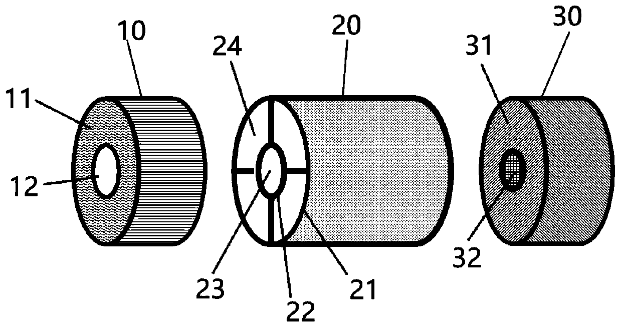
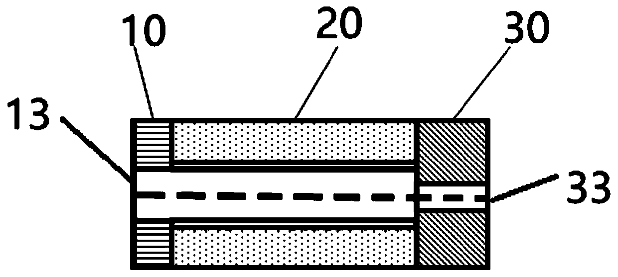
[0081] The profile of the aerosol cooling device of the present invention is basically a cylinder, and its circumference is about 22mm. The flow guiding part 10 includes a second tubular part 11, and the second tubular part 11 is a hollow cellulose acetate tow filter. The length of the tubular part 11 is about 5 mm, and the diameter of the radial section of the aerosol guide cavity 12 is about 3 mm; the heat insulating part 20 includes a first tubular part made of cornstarch, and the radial section of the first tubular part is as follows: Figure 8As shown, the length is 20mm, and the radial cross-sectional diameter of the aerosol flow chamber is 5mm; the mouthpiece part 30 includes an acetate fiber tow filter 31 and a flavoring matrix 32, and the flavoring matrix 32 is arranged on the tow filter 31 On the center line, the length of the tow filter 31 is about 8 mm, the flavoring base 32 is a flavoring gel, and the radial cross-sectional diameter of the flavoring base 32 is abou...
Embodiment 2
[0083] The shape of the aerosol cooling device of the present invention is basically a cylinder, and its circumference is about 22mm. The flow guiding part 10 includes a second tubular part 11, and the second tubular part 11 is a hollow polypropylene fiber tow filter. The length of the two tubular parts 11 is about 10 mm, and the radial cross-sectional diameter of the aerosol guide cavity 12 is about 3 mm; the heat insulating part 20 includes a first tubular part made of polyurethane resin, and the radial cross-section of the first tubular part is as follows: Figure 8 As shown, the length is 25mm, and the radial cross-sectional diameter of the aerosol flow chamber is 5mm; the mouthpiece part 30 includes a polylactic acid tow filter 31 and a flavoring matrix 32, and the flavoring matrix 32 is arranged on the tow filter 31 On the center line, the length of the tow filter 31 is about 8 mm, and the aroma-enhancing base 32 is a mint ice pop capsule with a particle size of 2.8 mm, p...
Embodiment 3
[0085] The profile of the aerosol cooling device of the present invention is basically a cylinder, and its circumference is about 22mm. The flow guiding part 10 includes a second tubular part 11, and the second tubular part 11 is a hollow cellulose acetate tow filter. The length of the tubular part 11 is about 8 mm, and the diameter of the radial section of the aerosol guide chamber 12 is about 4 mm; the heat insulating part 20 includes a first tubular part, made of polypropylene resin, and the radial section of the first tubular part is as follows: Figure 7 As shown, the length is 30mm, and the radial cross-sectional diameter of the aerosol flow chamber is 5mm; the mouthpiece part 30 includes a polylactic acid tow filter 31 and a flavoring matrix 32, and the flavoring matrix 32 is arranged on the tow filter 31 On the center line, the length of the tow filter 31 is about 8 mm, and the fragrance-enhancing base 32 is a fragrance-enhancing cotton thread loaded with menthol, and t...
PUM
 Abstract
Description
Claims
Application Information