A piezoelectric stack-driven drug injection device

A piezoelectric stacking and driving technology, which is applied in the field of medical devices, can solve the problems of unfavorable drug absorption and utilization, increase the burden on the heart, and have no therapeutic effect, so as to avoid uneven blood drug concentration, facilitate movement and portability, and prolong Effect of injection time

Active Publication Date: 2021-03-02
ZHEJIANG NORMAL UNIVERSITY
View PDF10 Cites 0 Cited by
  • Summary
  • Abstract
  • Description
  • Claims
  • Application Information

AI Technical Summary

Problems solved by technology

This infusion mode will bring many problems in actual use: the flow rate is adjusted manually, and the flow control accuracy is not enough; the infusion bottle needs to be held high by others when the patient walks or goes to the toilet, which is inconvenient to move and the height of the infusion bottle is not high enough. Make the blood flow back; patients or nurses need to be guarded for a long time, if the infusion is not found in time, it may cause accidents; the liquid medicine is in contact with the air, and the ambient air may be polluted when the air is unclean
In addition to the above direct problems, sometimes the infusion time is shortened by reducing the amount of solution, speeding up the infusion speed, etc., which not only increases the burden on the heart, but also affects the therapeutic effect: intramuscular injection and subcutaneous injection in a relatively short period of time. The biggest disadvantage of injecting into muscle or subcutaneous is that the blood drug concentration varies greatly within an injection cycle, which is not conducive to the effective absorption and utilization of drugs, because most drugs have a better concentration range in the human body, and when the drug concentration is too high Has toxic side effects, if it is too low, it will have no therapeutic effect

Method used


Image

  • A piezoelectric stack-driven drug injection device
  • A piezoelectric stack-driven drug injection device
  • A piezoelectric stack-driven drug injection device

Examples


Embodiment Construction

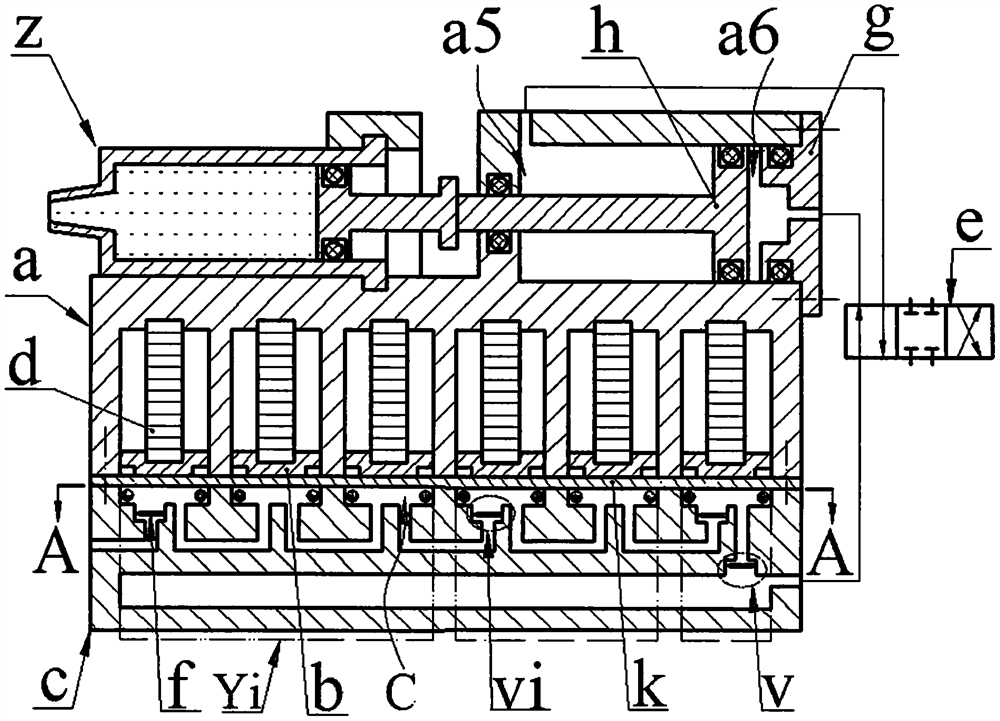
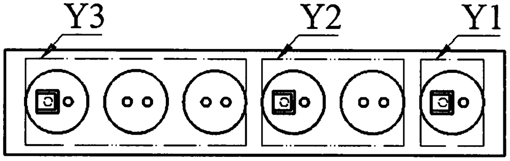
[0015] The base c is provided with an inlet hole c1, at least two sink cavity groups Ci consisting of sink cavity c2, an outlet cavity c3 and an air storage chamber c7, and the number of sink cavity c2 contained in each sink cavity group Ci increases sequentially from right to left The bottom wall of the leftmost sinking cavity c2 in each sinking cavity group Ci is provided with an inlet cavity c4 and an air outlet c5, and the bottom walls of other sinking cavities c2 are provided with an air inlet c6 and an air outlet c5; The inlet c4 in the cavity group Ci is connected with the inlet c1, the rightmost air outlet c5 in the rightmost sinking cavity group Ci is connected with the air storage chamber c7 through the outlet c3, and the rest of the same sinking cavity group Ci are two-phase The adjacent air inlet c6 is connected to the air outlet c5, and the adjacent outlet c5 in the left and right adjacent two cavity groups Ci is connected to the inlet c4; the inlet c4 and the outl...


PUM


Abstract

The invention relates to a piezoelectric stack-driven medicinal liquid injection device, which belongs to the field of medical instruments. A syringe is installed on the main body, and a cylinder chamber and a guide hole are provided. The cylinder chamber piston divides the cylinder chamber into left and right chambers. From right to left, the number of sink chambers, outlet chambers, and gas storage chambers are increasing; the leftmost sink cavity in each sink cavity group is equipped with inlet and outlet holes, and other sink chambers are equipped with inlet and outlet holes. The valve plate is installed in the inlet and outlet chambers; the main body is installed on the base and a diaphragm is pressed between them, the piezoelectric stack in the guide hole crimps the top block on the diaphragm, and the diaphragm crimps the sealing ring in the sink chamber to form a compression chamber; The compression chambers in the same sink chamber group are connected in parallel to form a compression chamber group, and each compression chamber group is connected in series; the left and right chambers are connected to the gas storage chamber through an air pipe and a reversing valve; during work, the deformation direction of the diaphragm in the same compression chamber group is the same. The deformation directions of the diaphragms in adjacent compression cavity groups are opposite.

Description

technical field [0001] The invention belongs to the field of medical equipment, and in particular relates to a piezoelectric stack-driven medicinal liquid injection device. Background technique [0002] Injection mainly includes intravenous injection, intramuscular injection and subcutaneous injection. Intravenous injection is also called infusion drug administration. Most of the existing infusion devices are composed of infusion bottles, infusion tubes and infusion stands. This infusion mode will bring many problems in actual use: the flow rate is adjusted manually, and the flow control accuracy is not enough; the infusion bottle needs to be held high by others when the patient walks or goes to the toilet, which is inconvenient to move and the height of the infusion bottle is not high enough. Make the blood flow back; the patient or the nursing staff need to watch for a long time, if the infusion is not found in time, it may cause an accident; the liquid medicine is in con...

Claims


Application Information

Patent Timeline
Patent Type & Authority Patents(China)
IPC IPC(8): A61M5/20A61M5/31
Inventor 吴鸣杜洁雅张子勍吴枫蓉阚君武温建明张敏
Owner ZHEJIANG NORMAL UNIVERSITY
Why Eureka
Try Eureka