
Thrombolytic balloon catheter device

A balloon catheter and thrombolysis technology, which can be applied to balloon catheters, drug devices, other medical devices, etc., can solve the problems of small contact area between thrombolytic drugs and thrombus, simple thrombolysis operation, and large outer diameter, etc. To achieve the effect of improving the thrombolytic effect, reducing the risk of falling off, and reducing the dosage

Active Publication Date: 2019-05-31
钟文
View PDF5 Cites 5 Cited by
  • Summary
  • Abstract
  • Description
  • Claims
  • Application Information

AI Technical Summary

Problems solved by technology

[0003] In order to overcome the shortcomings of the current rapid exchange reverse thrombolytic balloon catheter, the outer diameter of the distal section is too large, the thrombolytic operation is not simple enough, and the contact area between the thrombolytic drug and the thrombus is small, the perfusion thrombolytic balloon catheter device provided by the present invention It not only reduces the outer diameter of the catheter at the distal end of the catheter, but also prevents the balloon from entering the thrombus. It can also inject thrombolytic liquid into the thrombus in the entire segment at the same time, which increases the contact area between the thrombolytic drug and the thrombus, and improves the efficiency of thrombolysis. Thrombosis effect reduces thrombolytic drugs and simplifies thrombolytic operation

Method used


Image

  • Thrombolytic balloon catheter device
  • Thrombolytic balloon catheter device
  • Thrombolytic balloon catheter device

Examples


Embodiment Construction

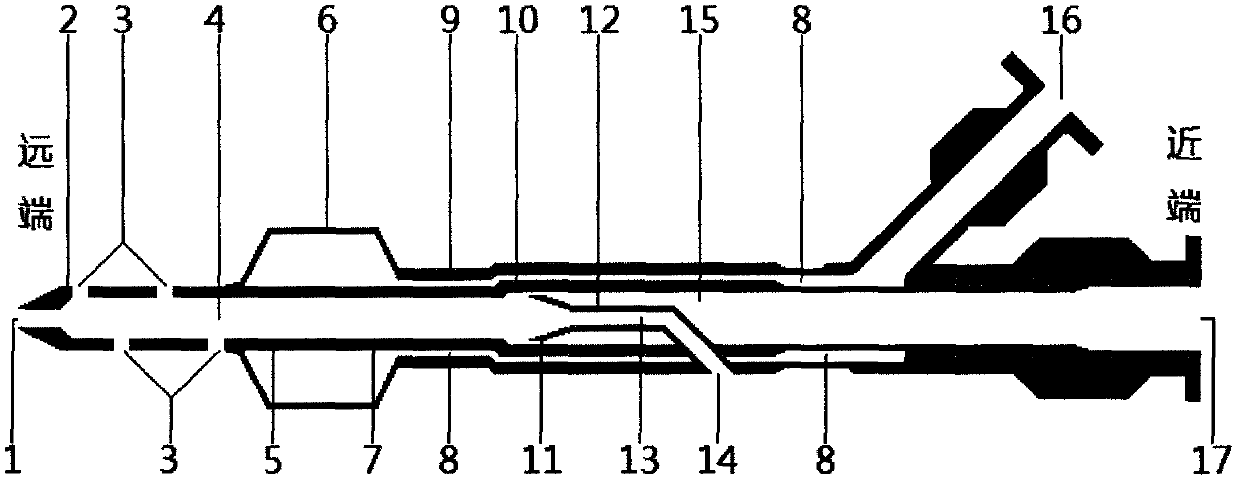
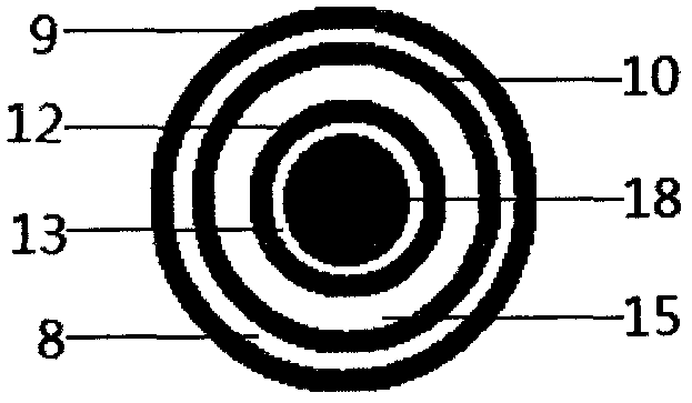
[0008] exist figure 1 Among them, the inner tube (10) runs through the entire length of the catheter, and its inner cavity is a connected perfusion cavity (15). The proximal end is provided with a drug injection port (17), and the distal section is sequentially provided with a balloon proximal ring mark (7), Balloon distal ring mark (5), multiple perfusion side holes opening in multiple directions (3), catheter distal ring mark (2) and guide wire entrance (1), in addition, the outer diameter of the inner tube distal It is gradually thickened to the nearest; the outer tube (9) is coaxially invaginated outside the inner tube (10) near the proximal end of the balloon (6), and the space between the inner and outer tubes is the balloon pressure and decompression cavity (8 ), the two ends of which are in communication with the balloon (6) and the pressure-reducing port (16) of the balloon respectively; The guide wire-perfusion common lumen (4) is coaxially pointing to the distal en...


PUM


Abstract

The invention provides a rapid exchange catheter device which can be used for thrombolysis in intracoronary thrombosis and percutaneous transluminal coronary angioplasty (PTCA). The device comprises aguide wire tube, an inner tube, an outer tube and a balloon. The middle distal section of the guide wire tube, the inner tube and the outer tube are coaxially overlapped from inside to outside; the proximal section of the guide wire tube penetrates through the wall of the inner tube and the wall of the outer tube to form a guide wire outlet, and the distal end of the guide wire tube is freely opened in the inner cavity of the inner tube; the inner cavity of the inner tube is a communicated perfusion cavity, the proximal end of the inner tube is provided with a medicine injection port, and thedistal section of the inner tube is provided with a perfusion side hole and a guide wire inlet which are opened in multiple directions; the cavity gap between the outer tube and the inner tube is a balloon pressurization and decompression cavity, the proximal end is provided with a balloon pressurization and decompression hole, and the distal end is communicated with the balloon cavity. Accordingto the invention, the functions of the thrombolytic catheter and the balloon catheter are integrated into one catheter, so that two operations of thrombolysis and PTCA in coronary artery thrombosis can be quickly completed, the thrombotic load can be reduced, the thromboembolism can be prevented, the operation time can be shortened, and the X-ray exposure to doctors and patients can be reduced.

Description

technical field [0001] The present invention relates to a fast-exchange catheter device that can be used for thrombolysis in coronary artery occlusive lesions, and can perform percutaneous transluminal coronary angioplasty (PTCA) on severe stenosis segments of occlusive lesions. In particular, it has the following two advantages: 1. It reduces the passing outer diameter of the distal end of the catheter, increases its passability, and reduces the risk of thrombus falling off due to extrusion, thereby preventing thromboembolism; The contact area of ​​the thrombus can further improve the thrombolytic effect, reduce the dosage of thrombolytic drugs, and reduce the risk of bleeding; 3. It simplifies the thrombolytic operation and shortens the X-ray exposure time of doctors and patients. Background technique [0002] At present, there is no thrombolytic balloon catheter available for clinical use. Only the patent document of the State Intellectual Property Office of the People's ...

Claims


Application Information

Patent Timeline
Patent Type & Authority Applications(China)
IPC IPC(8): A61M25/10A61M31/00
Inventor 钟文
Owner 钟文
Learn More