Retinal prosthesis, implant device and flexible cable

A retinal prosthesis and flexible cable technology, applied in the direction of eye implants, electrodes, internal electrodes, etc., can solve the problems of reduced battery life, uneven force, nerve damage, etc., to achieve increased service life, uniform distance, even force effect

Pending Publication Date: 2019-05-31
INTELLIMICRO MEDICAL CO LTD
View PDF0 Cites 5 Cited by
  • Summary
  • Abstract
  • Description
  • Claims
  • Application Information

AI Technical Summary

Problems solved by technology

[0002] In the related art, when the retinal prosthesis implantation device is implanted, usually only one retinal pin is implanted, so that there is only one fixed force point on the microelectrode, which easily causes the other side opposite to the retinal pin to warp Or the force is uneven, which leads to a larger distance between the stimulating electrodes on the microelectrodes and the retinal surface, and finally leads to the need for a larger stimulating current to produce better visual perception effects
[0003] Since the number of stimulating electrodes in the microelectrode is generally dozens, hundreds or even thousands, if a large proportion of the stimulating electrodes requires a large stimulating current, the total stimulating current will increase, which not only consumes electric energy, Reduced battery life and, in severe cases, nerve damage or seizures

Method used


Image

  • Retinal prosthesis, implant device and flexible cable
  • Retinal prosthesis, implant device and flexible cable
  • Retinal prosthesis, implant device and flexible cable

Examples


Embodiment Construction

[0050] Embodiments of the present invention are described in detail below, and the embodiments described with reference to the drawings are exemplary, and embodiments of the present invention are described in detail below.

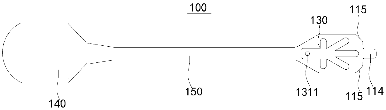
[0051] Refer below Figure 1-Figure 10 A flexible cable 100 for a retinal prosthesis according to an embodiment of the present invention is described.

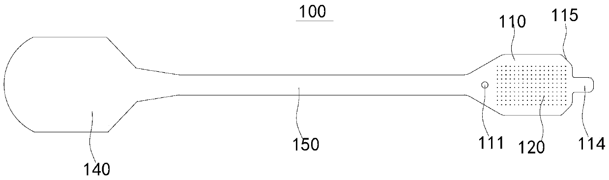
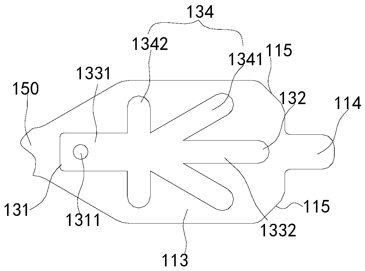
[0052] Such as Figure 1-Figure 6 As shown, the flexible cable 100 of the retinal prosthesis according to the embodiment of the present invention includes: a microelectrode 110 , a plurality of stimulating electrodes 120 , an abutment 130 , an introduction part 140 and a connection part 150 .

[0053] Such as figure 1 As shown, the microelectrode 110 has a first mounting hole 111 and an outer side of the first mounting hole 111 (for example, figure 1 The electrode area 112 on the right side in ). The electrode area 112 is generally located in the center of the microelectrode 110, and the first mounting...


PUM


Abstract

The invention discloses a flexible cable of a retinal prosthesis, which comprises a microelectrode, a plurality of stimulation electrodes, an abutting piece, a leading-in part and a connecting part, wherein the microelectrode is provided with a first mounting hole and an electrode region;the stimulation electrodes are arranged in the electrode region, and the end parts of the stimulation electrodes are exposed on one side surface of the microelectrode; the abutting piece is provided with a second mounting hole corresponding to the first mounting hole and extends to the back surfaces of the stimulation electrodes from the second mounting hole; the abutting piece is arranged on the other side surface of the microelectrode; force distribution obtained at the second mounting hole is transmitted to the back surfaces of the stimulation electrodes through elastic force generated by elastic denaturation, so that the electrodes are uniformly stressed, a better sticking effect is achieved, and the phenomena of inclination and warping of the electrodes caused by uneven stress are avoided.According to the flexible cable, the microelectrode can be uniformly stressed and can be better attached to the retina so as to obtain a more effective stimulation effect.The invention further discloses a retinal implant device and the retinal prosthesis.

Description

technical field [0001] The invention relates to the technical field of ophthalmic nerve stimulators, in particular to a flexible cable of a retinal prosthesis, an implantation device with the same, and a retinal prosthesis with the implantation device. Background technique [0002] In the related art, when the retinal prosthesis implantation device is implanted, usually only one retinal pin is implanted, so that there is only one fixed force point on the microelectrode, which easily causes the other side opposite to the retinal pin to warp Or uneven force, which in turn leads to a larger distance between some of the stimulating electrodes on the microelectrode and the retinal surface, and ultimately requires a greater intensity of stimulating current to produce a better visual perception effect. [0003] However, since the number of stimulating electrodes in a microelectrode is generally tens, hundreds or even thousands, if a large proportion of the stimulating electrodes re...

Claims


Application Information

Patent Timeline
Patent Type & Authority Applications(China)
IPC IPC(8): A61N1/36A61N1/05A61F2/14
Inventor 戴聿昌庞长林迪迪埃·萨根张旭曾维波
Owner INTELLIMICRO MEDICAL CO LTD
Why Eureka
Try Eureka