Full-automatic flange plate circumferential drilling device

A drilling device, a fully automatic technology, applied in the driving device, tangent device, tangent feeding device and other directions, can solve the problem of high manufacturing and maintenance costs, and achieve low manufacturing, maintenance costs, good reliability, and high degree of automation. Effect

Inactive Publication Date: 2019-05-31
JINHUA MINGZHENG TECH CO LTD
View PDF10 Cites 25 Cited by
  • Summary
  • Abstract
  • Description
  • Claims
  • Application Information

AI Technical Summary

Problems solved by technology

However, most of the existing flange hole processing equipment only has the function of tapping, and the flange position needs to be manually rotated. Some equipment with automatic position adjustment function rely on a large number of electronic components such as sensors and controllers. Use and maintenance costs are high

Method used


Image

  • Full-automatic flange plate circumferential drilling device
  • Full-automatic flange plate circumferential drilling device
  • Full-automatic flange plate circumferential drilling device

Examples


Embodiment 1

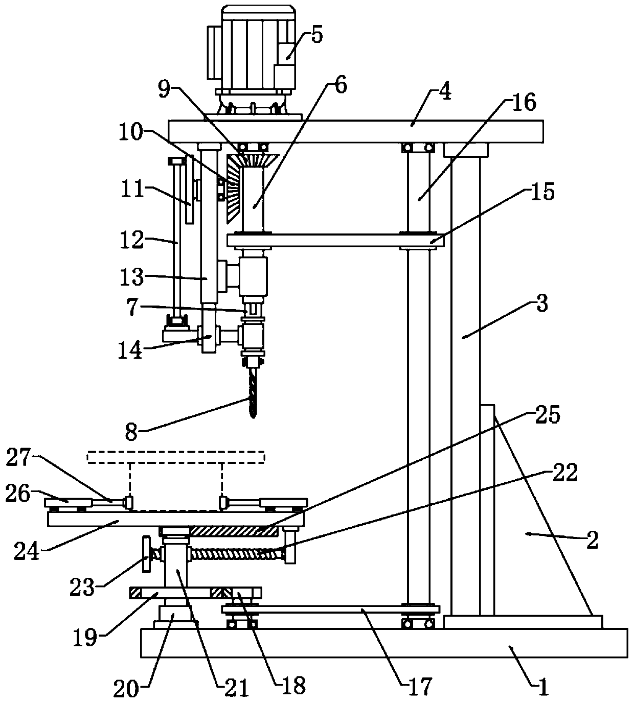
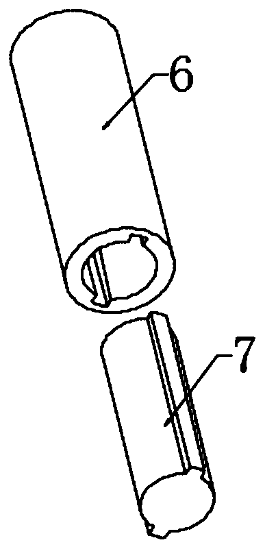
[0023] see Figure 1~4 , in an embodiment of the present invention, a fully automatic flange circumferential drilling device, including a base plate 1, an output shaft 6, a tap 8, a telescopic plate 14 and a platform 24; 3. The upper end of the back plate 3 is fixedly connected to the top plate 4, and the flange on the top plate 4 is connected to the drive motor 5, and the lower part of the drive motor 5 is connected to the output shaft 6 in rotation, and the output shaft 6 passes through the top plate 4 and is connected to the bearing in rotation, wherein the drive motor 5 wires are connected to the power supply and the switch, and the switch is turned on so that the drive motor 5 is powered on and energized to drive the output shaft 6 to rotate; the lower part of the output shaft 6 is socketed with the driven shaft 7, specifically, the output shaft 6 is hollow, and the inner wall of the output shaft 6 is hollow. Two grooves are symmetrically arranged, and the outer surface o...

Embodiment 2

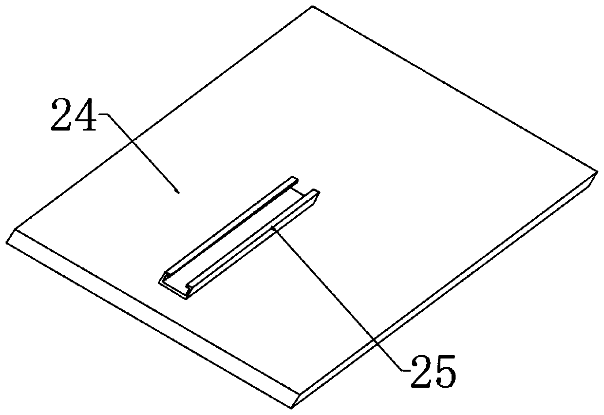
[0027] In order to further explain the above-mentioned fully automatic flange circumferential drilling device, the application provides another embodiment, the fully automatic flange circumferential drilling device in this embodiment has the following technical features: the platform 24 Cylinders 26 are symmetrically fixed on both sides of the upper side, and one side of the cylinder 26 is sealed and slidably connected to the piston rod 27. The end of the piston rod 27 is fixed with a clamp 28. The clamp 28 is arc-shaped. The thinner part of the lower part of the flange is clamped to prevent the flange from moving when drilling.

[0028]According to the specific description of the above embodiments, it is easy to know that the working principle of the present invention is: turn on the switch to make the drive motor 5 turn on the power and work to drive the output shaft 6 to rotate, and the output shaft 6 can drive the driven shaft through the cooperation of the convex strip and...


PUM


Abstract

The invention discloses a full-automatic flange plate circumferential drilling device, and particularly relates to equipment for automatically machining circumferential flanges holes of a flange. An output shaft drives a driven shaft and a screw tap to rotate, the rotating output shaft drives a rotating wheel to rotate through a bevel gear group, the rotating wheel drives a telescopic plate to vertically move in a reciprocating mode through a connecting rod to drive the screw tap to rotate at high speed and vertically move simultaneously, the output shaft drives an incomplete gear to rotate through a synchronous belt and a rotation shaft, the incomplete gear drives a large gear and a platform supporting shaft to intermittently rotate to drive a platform and a flange plate to intermittentlyrotate, and then circumferential equal-distance drilling integrated work is achieved. According to the full-automatic flange plate circumferential drilling device, the automation degree is high, andthe synchronism is high; and through mechanical transmission, the connection reliability is good, the manufacture, use and maintenance cost is low, and the problems that when an existing flange plateis drilled, rotation of the flange plate needs to be manually controlled, parts of equipment with an automatic control function uses a large quantity of electronic components, and the manufacture anduse cost is high are effectively solved.

Description

technical field [0001] The invention relates to a mechanical processing equipment, in particular to a fully automatic peripheral drilling device for a flange. Background technique [0002] Flange is also called flange flange or flange. Flanges are parts that are connected to each other between pipes and are used for connection between pipe ends; they are also useful for flanges on equipment inlets and outlets, And can be used as connection between two equipments, example reducer flanges. Flange connection or flange joint refers back to the detachable connection of flange, Gasket and bolt as a team of combined sealing structure. [0003] Flanges are used in pairs, and low-pressure pipelines can use wire flanges. Holes are equidistant around the flange, and bolts are used to match the flange holes to tightly connect the two flanges. However, most of the existing flange hole processing equipment only has the function of tapping, and the flange position needs to be manually ro...

Claims


Application Information

Patent Timeline
Patent Type & Authority Applications(China)
IPC IPC(8): B23G1/18B23G11/00B23Q5/10B23Q1/52
Inventor 马双斌
Owner JINHUA MINGZHENG TECH CO LTD
Why Eureka
Try Eureka