Large field-of-view galvanometer coaxial vision imaging device and method

An imaging method and a technology with a large field of view, applied in welding equipment, laser welding equipment, metal processing equipment, etc., can solve the problems of inability to shoot larger samples at one time, small visual format, increased cost, and cumbersome debugging, etc., to achieve Improve the coaxial visual format of the galvanometer and overcome the effect of positioning deviation

Active Publication Date: 2019-05-31
WUHAN HGLASER ENG CO LTD
View PDF10 Cites 2 Cited by
  • Summary
  • Abstract
  • Description
  • Claims
  • Application Information

AI Technical Summary

Problems solved by technology

However, the visual format of the existing laser coaxial positioning and detection is relatively small. Generally, the maximum compatible image sensor is 1 / 2 inch. The short side of the field lens image sensor with the F170 has a visual format of about 12mm, and it is impossible to shoot large samples at one time. , the visual positioning function cannot be completed. An existing method is to use two visual systems, the system with a small visual format for position compensation, and the system with a large visual format for positioning (citing patents: CN105598579A, 20160525, visual positioning based on two coaxial laser processing device and method), on the one hand, this solution increases the cost and cumbersome debugging, on the other hand, the stability and cooperation between the system and the two image sensors are very high, and it is not flexible and convenient to use.

Method used


Image

  • Large field-of-view galvanometer coaxial vision imaging device and method
  • Large field-of-view galvanometer coaxial vision imaging device and method
  • Large field-of-view galvanometer coaxial vision imaging device and method

Examples


Embodiment Construction

[0032] The following will clearly and completely describe the technical solutions in the embodiments of the present invention with reference to the accompanying drawings in the embodiments of the present invention. Obviously, the described embodiments are only a part of the present invention, not all embodiments. Based on the embodiments of the present invention, all other embodiments obtained by persons of ordinary skill in the art without making creative efforts belong to the protection scope of the present invention.

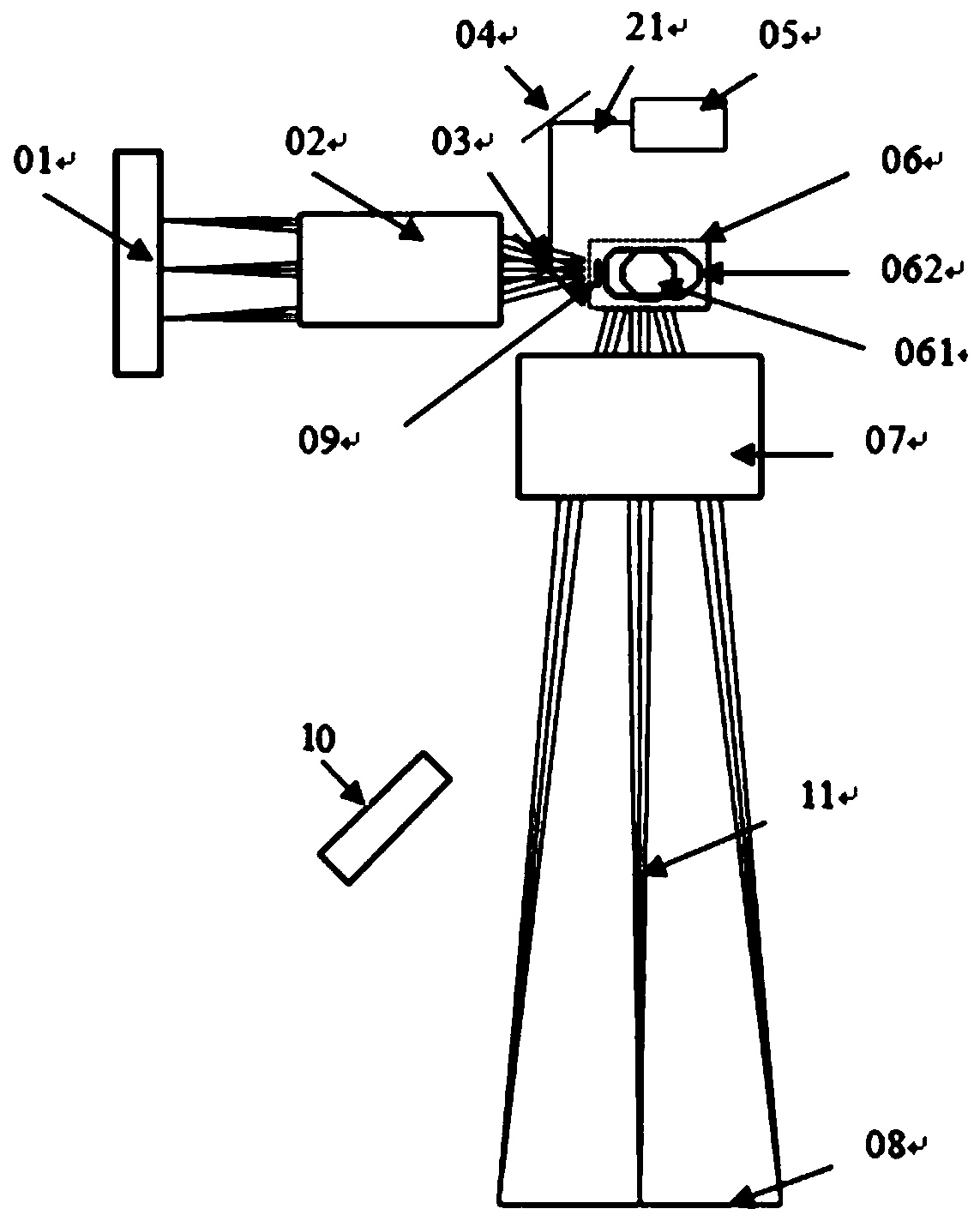
[0033] Such as figure 1 As shown, as the first aspect of the present invention, a large field of view galvanometer coaxial visual imaging device is provided, the device includes a light source 10, a field lens 07, a galvanometer system 06, an aperture component 09, a beam splitter 03, The imaging lens 02, the image sensor 01, and the laser assembly, the image sensor 01, the imaging lens 02, the aperture part 09 and the vibrating mirror system 06 are arranged ...


PUM


Abstract

The invention discloses a large field-of-view galvanometer coaxial vision imaging device and method. The device comprises a light source, a field lens, a galvanometer system, a diaphragm portion, a spectroscope, an image sensor and a laser assembly; the light source is used for irradiating a to-be-machined workpiece surface, and an imaging system light beam reflected by the workpiece surface sequentially passes through the field lens, the galvanometer system, the diaphragm portion and the spectroscope, enters a camera shooting lens and is received through the image sensor; and a laser light beam emitted by the laser assembly sequentially passes through the spectroscope, the diaphragm portion, the galvanometer system and the field lens and irradiates the to-be-machined workpiece surface. According to the large field-of-view galvanometer coaxial vision imaging device and method, the galvanometer coaxial vision breadth can be significantly increased, a visual positioning function of a large sample is completed by directly adopting galvanometer coaxial vision in the laser machining process, and positioning deviation caused by temperature drift of the galvanometer system in a laser machining system is overcome.

Description

technical field [0001] The invention relates to the field of vibrating mirror coaxial visual imaging, and specifically relates to a large field of view vibrating mirror coaxial visual imaging device and method. Background technique [0002] Laser processing has been widely used in modern manufacturing, especially in the fields of precision processing and micro-processing, including cutting, marking, printing, drilling, engraving, scanning, etc. Flexible adaptability, intelligence and efficiency requirements are getting higher and higher, so laser processing systems with visual positioning and detection are becoming more and more popular. Laser processing systems with visual positioning generally have two methods, one is paraxial vision , the machine vision imaging lens is placed on the side of the laser processing head, and the vision system and the laser processing system are independent of each other; the other is the coaxial vision, which means that the vision positioning...

Claims


Application Information

Patent Timeline
Patent Type & Authority Applications(China)
IPC IPC(8): B23K26/064B23K26/082
Inventor 王雪辉王建刚雷桂明许维温彬喻浩
Owner WUHAN HGLASER ENG CO LTD
Why Eureka
Try Eureka