Reinforcing steel bar binding moulding bed frame for prefabricating T-beam wing plate and use method

A technology of steel bar binding and beam wing plate, applied in the direction of manufacturing tools, ceramic molding machines, etc., can solve the problems affecting T-beam pouring, bellows are easy to shift, T-beam binding wing plate takes a long time, etc., to improve work efficiency and Quality of work, simple structure, time-consuming effects to solve

Inactive Publication Date: 2019-05-31
CHINA MCC17 GRP
View PDF6 Cites 0 Cited by
  • Summary
  • Abstract
  • Description
  • Claims
  • Application Information

AI Technical Summary

Problems solved by technology

[0004] The purpose of the present invention is to solve the problems that the T-beam binding flange proposed in the above-mentioned background technology takes a long time, affects the T-beam pouring, and the bellows of the negative moment part on the T-beam flange are easy to shift.

Method used


Image

  • Reinforcing steel bar binding moulding bed frame for prefabricating T-beam wing plate and use method
  • Reinforcing steel bar binding moulding bed frame for prefabricating T-beam wing plate and use method
  • Reinforcing steel bar binding moulding bed frame for prefabricating T-beam wing plate and use method

Examples


Embodiment 1

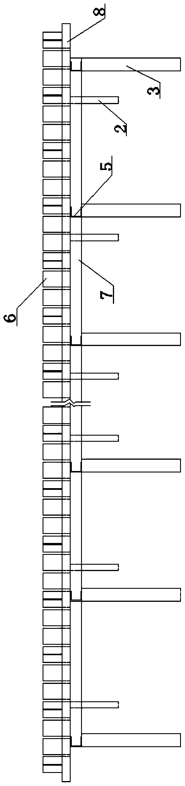
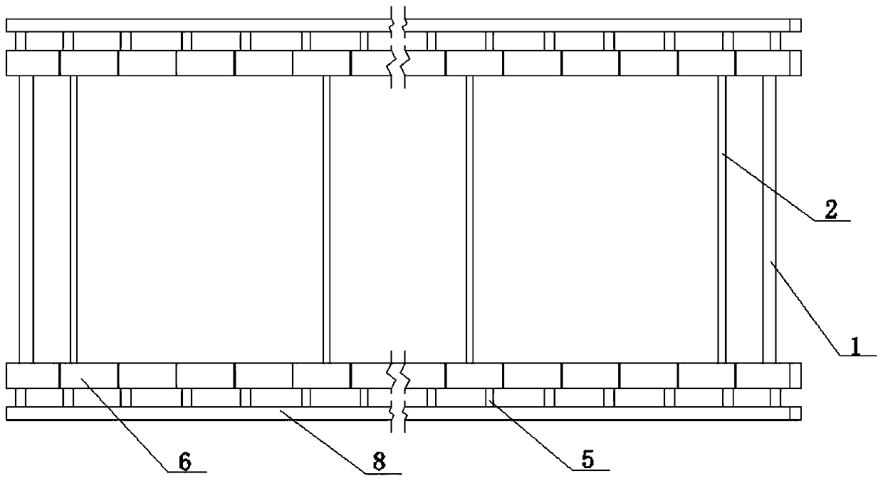
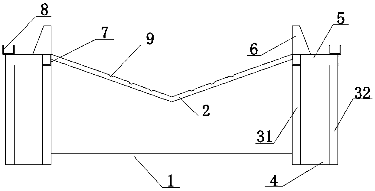
[0036] As attached to the manual Figures 1 to 4 The shown prefabricated T-beam wing plate steel bar binding tire formwork includes a plurality of connecting rods 1 arranged in parallel, each connecting rod 1 is provided with two main poles 3 at both ends, and the two main poles 3 includes the first main pole 31 and the second main pole 32, the two ends of the connecting rod 1 are welded with the first main pole 31, and the top ends of the first main pole 31 at both ends of the connecting rod 1 are welded respectively There is a main beam 7, and a plurality of V-shaped brackets 2 are welded equidistantly between the main beams 7 on the same side. The upper surface of the V-shaped bracket 2 is provided with a plurality of bellows positioning grooves 9, and the main beam 7 on the same side is far away from the The surface of the side wall of the V-shaped bracket 2 is equidistantly welded with a plurality of upper fixing rods 5, and the upper surface of the upper fixing rod 5 awa...

Embodiment 2

[0044] A method for using a steel bar binding tire formwork for prefabricating a T-beam wing plate, comprising the following specific implementation steps:

[0045] Step 1: Set up the reinforcing bars for positioning, and insert the two rows of reinforcing bars for positioning into the ground at the designated position at a certain interval;

[0046] Step 2, the first main pole 31 and the second main pole 32 are welded with reinforcing bars for positioning;

[0047] Step 3, the lower fixed rod 4 and the upper fixed rod 5 are respectively connected to the first main vertical rod 31 and the second main vertical rod 32 for horizontal welding and fixing, and the lower fixed rod 4 is welded to the steel bar for positioning;

[0048] Step 4, use connecting rod 1 to connect below the first main poles 31 in two horizontal rows;

[0049] Step 5, use the main crossbeam 7 to connect above the first vertical main pole 31 of each row;

[0050] Step 6, multiple V-shaped brackets 2 are welde...


PUM


Abstract

The invention provides a reinforcing steel bar binding moulding bed frame for prefabricating T-beam wing plate and a use method in order to achieve the aim. The reinforcing steel bar binding mouldingbed frame comprises multiple connecting rods arranged in parallel, and two main stand rods are arranged at the two ends of each connecting rod and comprises a first main stand rod and a second main stand rod. The two ends of each connecting rod are welded to the corresponding first main stand rods, and main cross beams are welded to the top ends of the first main stand rods correspondingly. Multiple V-shaped brackets are welded between the main cross beams on the same side at equal intervals, and multiple corrugated pipe locating grooves are formed in the surfaces of the upper ends of the V-shaped brackets. The reinforcing steel bar binding moulding bed frame is simple in structure and convenient to manufacture, the work efficiency and work quality are improved, and waste caused in the construction process is effectively reduced; and the problems that T-beam wing plate binding consumes long time, T-beam pouring is influenced, and a corrugated pipe on the hogging moment portion of the T-beam wing plate is likely to shift are solved.

Description

technical field [0001] The invention relates to the technical field of building construction, in particular to a prefabricated T-beam wing plate steel bar binding tire formwork and a use method. Background technique [0002] In recent years, under the guidance of national policies, the country's infrastructure has developed rapidly, especially in the southwest of my country, which is mostly mountainous and hilly, and the roads built include a large number of bridge projects. Many of the current highway bridge designs use T-beam structures, which makes driving on highway bridges more stable and comfortable. [0003] At present, the production process of prefabricated T-beams is relatively complicated. Among them, in the binding of T-beam reinforcement skeleton structure, for the binding of wing plate reinforcement, the general method is that after the T-beam formwork is installed, workers directly bind the wings on the top of the T-beam rib. Plates take a long time and affec...

Claims


Application Information

Patent Timeline
Patent Type & Authority Applications(China)
IPC IPC(8): B28B23/14
Inventor 郑志伟杨兵原正峰史纪申
Owner CHINA MCC17 GRP
Why Eureka
Try Eureka