Fixture for processing injection mold
A technology for injection molds and fixtures, which is applied in the field of fixtures for injection mold processing, can solve the problems of high labor intensity, high cost of fixing injection molds, inability to adapt to different sizes and models of injection molds, etc., and achieve low cost and low labor intensity Effect
- Summary
- Abstract
- Description
- Claims
- Application Information
AI Technical Summary
Problems solved by technology
Method used
Image
Examples
specific Embodiment approach 1
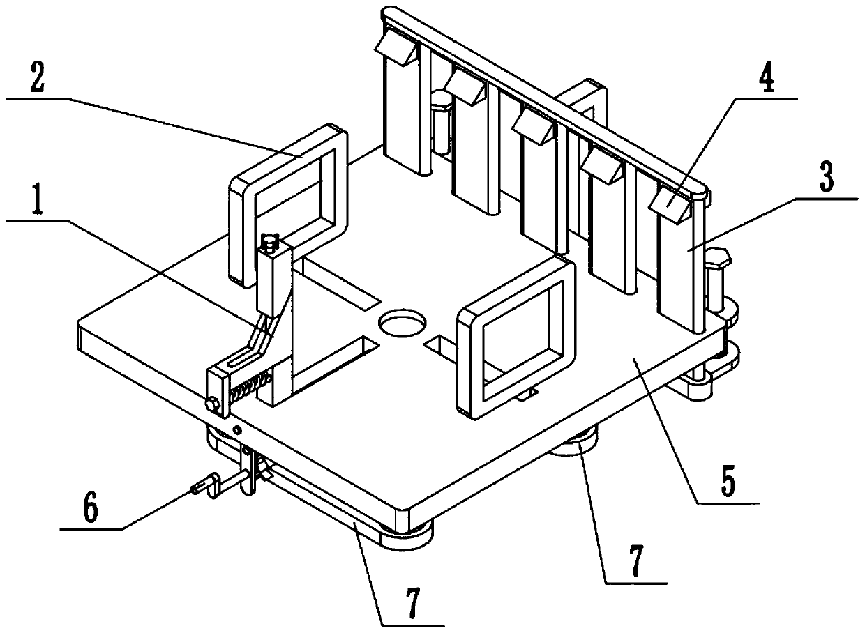
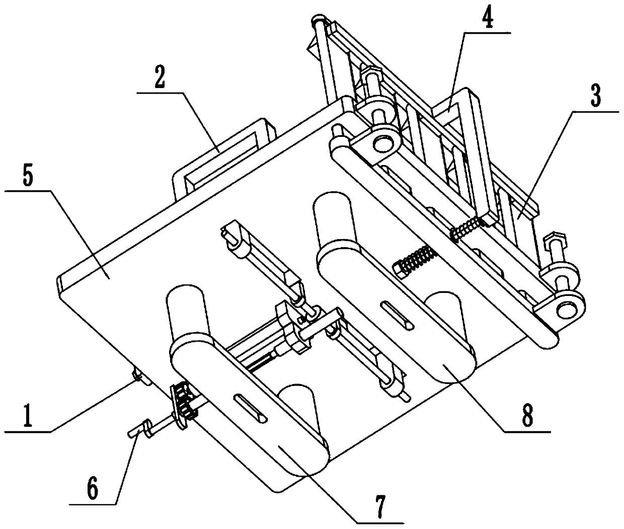
[0025] Such as Figure 1-11 As shown, a fixture for injection mold processing includes a front clamping mechanism 1, a left and right clamping mechanism 2, a rear clamping mechanism 3, an upper clamping mechanism 4, a horizontal supporting plate 5, a clamping control mechanism 6 and a vertical clamping mechanism. frame 7, the front end of the horizontal supporting plate 5 is provided with front and rear sliding holes 5-1, the left and right sides of the middle end of the horizontal supporting plate 5 are respectively provided with a left and right sliding hole 5-2, and the rear ends of the horizontal supporting plate 5 are evenly arranged side by side a plurality of slot-shaped sliding holes 5-3; the inner side of the front and rear sliding holes 5-1 is fixedly connected to the guide shaft; The side tightening mechanism 1 is connected with the guide shaft in a sliding fit; the jacking control mechanism 6 is fixedly connected to the bottom surface of the horizontal pallet 5, an...
specific Embodiment approach 2
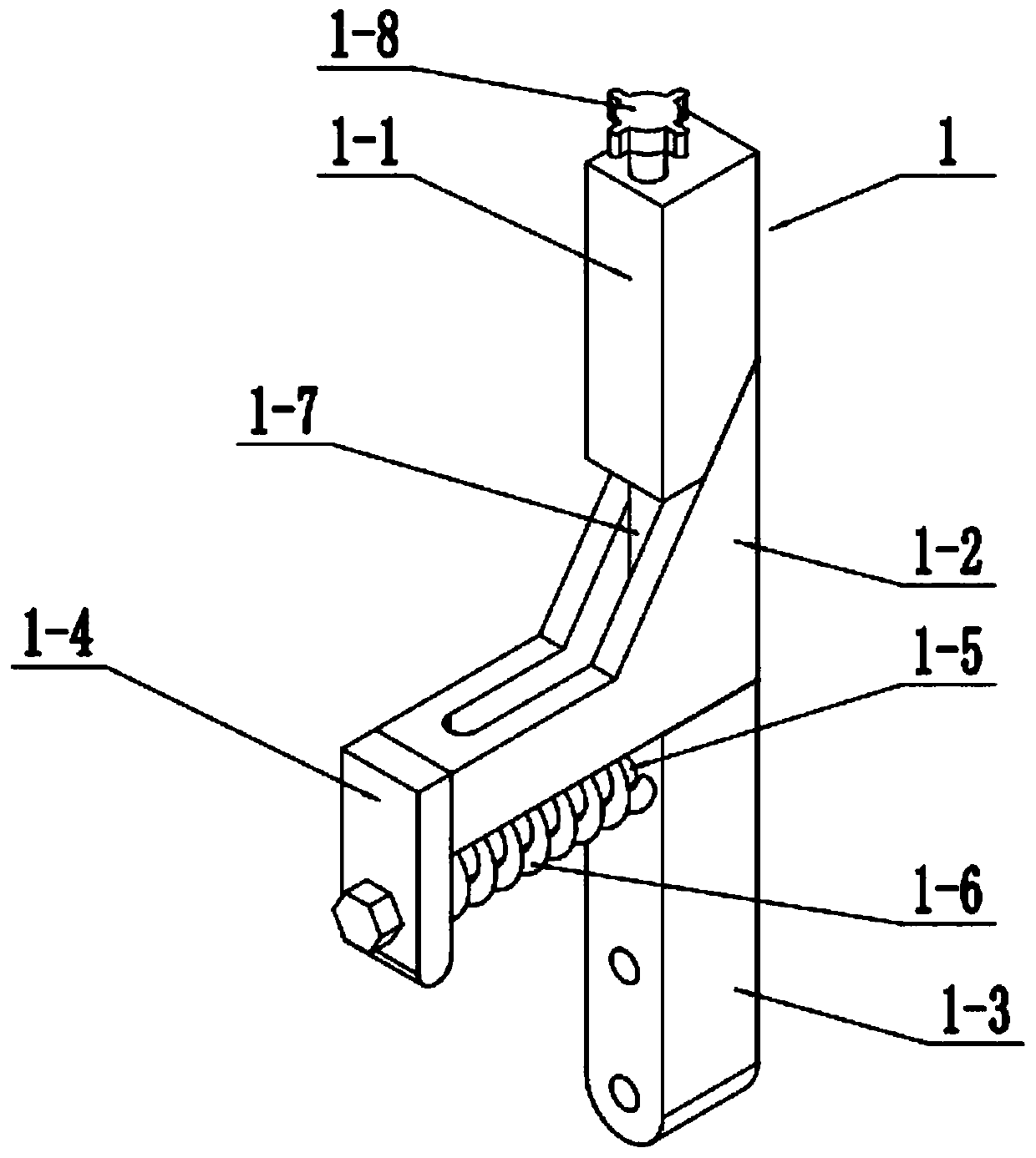
[0026] Such as Figure 1-11As shown, the front side tightening mechanism 1 includes an upper top block 1-1, a middle top block 1-2, a lower top block 1-3, a movable plate 1-4, a spring rod 1-5, and a compression spring 1-6 , screw rod 1-7 and rotating block 1-8; the slope of the bottom surface of the upper top block 1-1 is slidingly matched with the slope of the top surface of the middle top block 1-2; the bottom surface of the middle top block 1-2 is slidingly fitted and connected On the top surface of the lower jacking block 1-3; the front end of the middle jacking block 1-2 is fixedly connected to the movable plate 1-4; the front end of the spring rod 1-5 is slidably connected to the movable plate 1-4, and the spring The rear end of the rod 1-5 is fixedly connected to the lower top block 1-3, and the spring rod 1-5 between the movable plate 1-4 and the lower top block 1-3 is provided with a stage clip 1-6; The top block 1-3 is slidably connected in the front and rear slidi...
specific Embodiment approach 3
[0027] Such as Figure 1-11 As shown, the left and right tightening mechanism 2 includes a worm wheel 2-1, a two-way screw 2-2, a rod frame plate 2-3, a left and right slider 2-4 and a left and right top plate 2-5; the worm wheel 2-1 is fixedly connected At the middle end of the two-way screw rod 2-2, the two-way screw rod 2-2 is rotatably connected on the two rod frame plates 2-3 through a bearing with a seat, and the two rod frame plates 2-3 are fixedly connected to the bottom surface of the horizontal supporting plate 5 respectively. The left and right ends; the left and right ends of the two-way screw 2-2 are respectively threaded to a left and right slider 2-4, and the two left and right sliders 2-4 are symmetrically slidingly fitted and connected in the two left and right sliding holes 5-2; The upper ends of the two left and right sliders 2-4 are respectively fixedly connected with a left and right top plate 2-5; the top tight control mechanism 6 is engaged with the tran...
PUM
 Abstract
Description
Claims
Application Information
 - R&D
- Intellectual Property
- Life Sciences
- Materials
- Tech Scout
- Unparalleled Data Quality
- Higher Quality Content
- 60% Fewer Hallucinations
Browse by: Latest US Patents, China's latest patents, Technical Efficacy Thesaurus, Application Domain, Technology Topic, Popular Technical Reports.
© 2025 PatSnap. All rights reserved.Legal|Privacy policy|Modern Slavery Act Transparency Statement|Sitemap|About US| Contact US: help@patsnap.com


