A method for preparing a composite fuel tank by using an integral molding die

A composite material and integral forming technology, which is applied in the field of aviation composite material forming, can solve problems such as the integral forming method of fuel tanks without composite materials, and achieve the effect of avoiding huge workload and inspection workload, reducing gaps, and combining densely

Active Publication Date: 2021-01-01
GUANGLIAN AVIATION IND CO LTD
View PDF6 Cites 0 Cited by
  • Summary
  • Abstract
  • Description
  • Claims
  • Application Information

AI Technical Summary

Problems solved by technology

[0004] The purpose of the present invention is to provide a method for preparing a composite material fuel tank by using an integral forming mold to solve the problem that there is no integral forming method for a composite material fuel tank at present

Method used


Image

  • A method for preparing a composite fuel tank by using an integral molding die
  • A method for preparing a composite fuel tank by using an integral molding die
  • A method for preparing a composite fuel tank by using an integral molding die

Examples


specific Embodiment approach 1

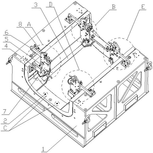
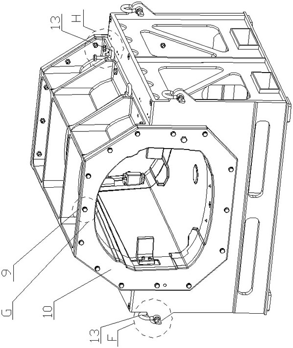
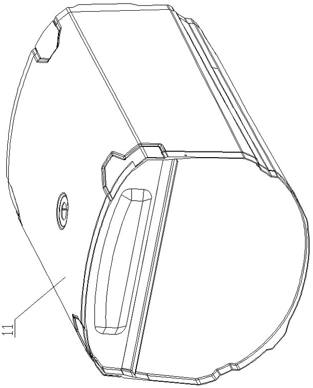
[0053] Specific Embodiment 1: This embodiment discloses a method for preparing a composite fuel tank using an integral molding die, the method includes the following steps (see Figure 1-Figure 13 ):

[0054] Step 1: Positioning the two cured end frames 12-1;

[0055] The two cured end frames 12-1 are placed upright against the left and right ports of the cavity of the lower mold 1, and the bottom surfaces of the left and right ports of the cavity of the lower mold 1 are connected to the corresponding end frames through two positioning pins 2 respectively. Frame 12-1 positioning connection (two round holes are respectively provided on the bottom surface of the left and right ports of the mold cavity of the lower mold 1, and each of the round holes is interference fit with one end of a positioning pin 2, and each end frame 12 -1 is provided with two positioning holes corresponding to the two positioning pins 2, and positioning pins 2 are interference fit in each positioning ho...


PUM

PropertyMeasurementUnit
lengthaaaaaaaaaa

Abstract

The invention provides a method for preparing a composite fuel tank by using an integral molding mold and belongs to the field of molding of aeronautical composites. The method comprises the steps: step 1, positioning end frames on a lower mold; step 2, placing process dummies on the inner bottom surface of a mold cavity of the lower mold, positioning beams, and gluing the beams and the end framestogether to form a fuel tank skeleton; step 3, removing the fuel tank skeleton and the process dummies, and assembling an upper mold, the lower mold and end plates into the molding mold by using sealing rubber strips; step 4, laying a composite layers in a mold cavity of the molding mold and pre-compacting the composite layers to obtain a fuel tank skin, and reserving an overlapping area; step 5,detaching the upper mold and the end plates, opening the pre-compacted fuel tank skin, mounting and positioning the fuel tank skeleton in the mold cavity of the lower mold, and closing the fuel tankskin; step 6, remounting the upper mold and the end plates; and step 7, performing curing and demoulding. According to the composite fuel tank prepared by the method, a complex skin reinforced structure can be manufactured, and the product is light, not liable to leak, and high in structural performance.

Description

technical field [0001] The invention belongs to the field of aviation composite material molding, and in particular relates to a method for preparing a composite material fuel tank by using an integral molding die. Background technique [0002] Most of the present airplanes are powered by fuel engines, and fuel tanks for storing fuel need to be provided on the airplanes so as to continuously provide fuel for the engines, so that the airplanes can obtain continuous power and keep flying in the air. A general aircraft has three major fuel tanks. The central fuel tank is located in the lower part of the cabin in the middle of the aircraft and stores the largest amount of fuel. Next is exactly to be arranged on the wing fuel tank in the wing of fuselage both sides and the additional central fuel tank that is arranged on fuselage lower part. In the past, fuel tanks were composed of structural parts, which were riveted into a whole by rivets. In order to overcome the gravity and ...

Claims


Application Information

Patent Timeline
Patent Type & Authority Patents(China)
IPC IPC(8): B29C70/44B29C70/46B29C70/54
Inventor 刘凤艳杨智儒邹鹏郭金亮王丹丹
Owner GUANGLIAN AVIATION IND CO LTD
Why Eureka
Try Eureka