Hydrodynamic cavitation device for pharmaceutical wastewater treatment

A technology for hydrodynamic cavitation, pharmaceutical wastewater, applied in natural water treatment, oxidized water/sewage treatment, water/sludge/sewage treatment, etc. The effect of improving the treatment effect, improving the cavitation efficiency, and improving the treatment efficiency

Inactive Publication Date: 2019-05-31
SHANDONG UNIV
View PDF2 Cites 0 Cited by
  • Summary
  • Abstract
  • Description
  • Claims
  • Application Information

AI Technical Summary

Problems solved by technology

[0004] At present, the conventional hydraulic cavitation reactor is a single Venturi tube or orifice cavitator, with simple cavitation structure and low cavitation effect
However, pharmaceutical wastewater has many macromolecular substances that are difficult to degrade and treat. Pharmaceutical wastewater has a complex composition, many types of organic pollutants, high concentrations, high values ​​and large fluctuations, large differences in wastewater values, long wastewater treatment process routes, and high treatment costs.
Therefore, the existing hydraulic cavitator has low efficiency and unsatisfactory treatment effect in pharmaceutical wastewater treatment.

Method used


Image

  • Hydrodynamic cavitation device for pharmaceutical wastewater treatment

Examples


Embodiment Construction

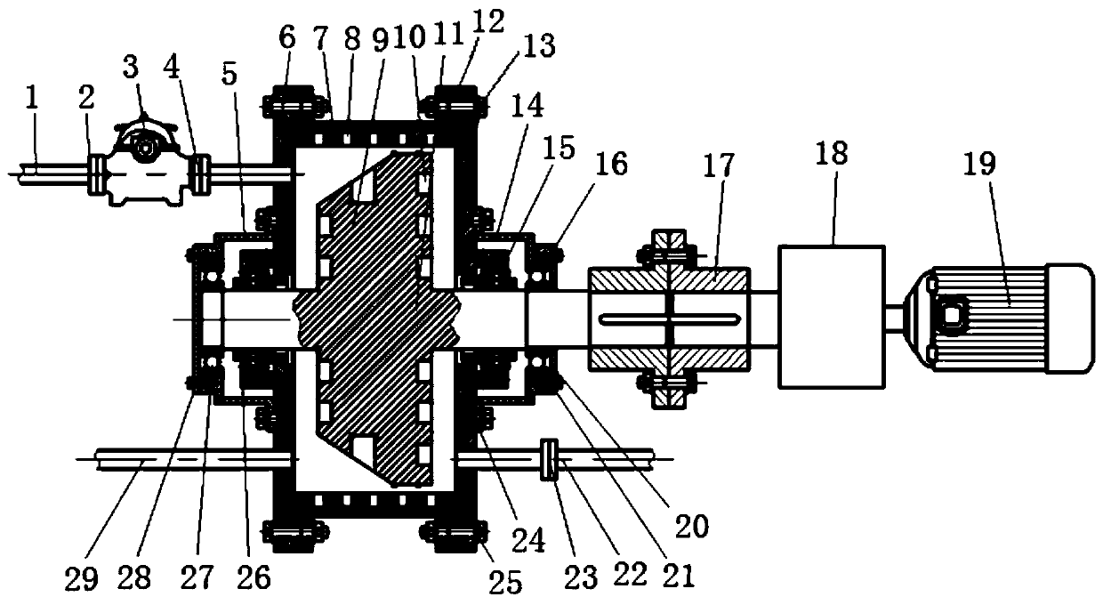
[0023] The hydraulic cavitator for pharmaceutical wastewater treatment of the present invention, such as figure 1 As shown, it includes a stator 7, a rotor 9 and a rotating shaft 11, and the stator 7 can be fixed on the foundation. A cavitation cavity is formed inside the stator 7 . Both ends of the stator 7 are connected with a stator left end cover 6 and a stator right end cover 13 by bolts 25, and a sealing gasket 12 is arranged between the stator 7 and its left and right end covers. The stator 7 and its left end cover 6 and right end cover 13 form a cavitation cavity. Stator blind holes 8 are distributed on the inner wall of the cavitation chamber. The depth of the stator blind holes 8 is 40mm and the diameter is 20mm.

[0024] The stator left end cover 6 and the stator right end cover 13 are respectively connected with the bearing left support cover 5 and the bearing right support cover 14 by screws 24, and the bearing left support cover 5 and the bearing right support ...


PUM

PropertyMeasurementUnit
depthaaaaaaaaaa
diameteraaaaaaaaaa
depthaaaaaaaaaa

Abstract

The invention provides a hydrodynamic cavitation device for pharmaceutical wastewater treatment. The hydrodynamic cavitation device comprises a stator, a rotor and a rotary shaft. A cavitation cavityis formed in the stator, and a stator blind hole is distributed on the inner wall of the cavitation cavity. The rotary shaft is mounted in the rotor, one end of the rotary shaft stretches out of the stator, and the stretching-out end is connected with a transmission device. The rotor is a conical rotary disc, and is arranged in the cavitation cavity and fixedly connected to the rotary shaft, and arotor blind hole is formed in the outer wall of the rotor. A water inflow pipeline and a reagent pipeline are arranged at one end of the stator, and a water outflow pipeline is arranged at the otherend of the stator. Pharmaceutical wastewater is purified through the cavitation phenomenon, the pharmaceutical wastewater is pressed into the hydrodynamic cavitation device through pressure of a waterpump, cavitation bubbles are generated in the hydrodynamic cavitation device through mechanical rotation, by means of energy released in the generation to collapse process of the cavitation bubbles,macromolecules hardly treated in the sewage are degraded into micromolecules easily decomposed, a sufficient oxidation reaction can be carried out due to the addition of a Fenton's reagent, and the pharmaceutical wastewater is treated.

Description

technical field [0001] The invention relates to a device for purifying pharmaceutical wastewater through hydraulic cavitation, and belongs to the technical field of water treatment of hydraulic cavitation. Background technique [0002] Medical wastewater has complex components, high concentration and salinity, high chroma and toxicity, and often contains a wide variety of organic pollutants. Many of these substances are difficult to biodegrade and can remain in the environment for a long time. Especially the carcinogenic, teratogenic and mutagenic organic pollutants, which are extremely harmful to human health, will seriously endanger human health even when the concentration in water is very low. The treatment of these various and complex organic wastewater is still a difficult and hot point in water treatment. [0003] Cavitation refers to the process of the formation, development and collapse of gas cavities inside the liquid or on the liquid-solid interface when the loca...

Claims


Application Information

Patent Timeline
Patent Type & Authority Applications(China)
IPC IPC(8): C02F1/72C02F101/30C02F103/34
Inventor 孙逊陈颂英陈晓航寇清民张孝添马训孟
Owner SHANDONG UNIV
Why Eureka
Try Eureka