Reciprocating type compressor indicator diagram testing device and fault diagnosis method

A compressor and dynamometer technology, which is applied in the field of reciprocating compressor dynamometer testing devices, can solve the problems of inertia error, the compressor speed cannot be too high, and the dynamometer cannot be accurately measured, and the convergence speed is fast. Effect

Inactive Publication Date: 2019-05-31
YANGTZE UNIVERSITY
View PDF0 Cites 9 Cited by
  • Summary
  • Abstract
  • Description
  • Claims
  • Application Information

AI Technical Summary

Problems solved by technology

Therefore, the working process of this mechanism is the synthesis of two vibration systems, and this system will have inertial errors during the measurement pro

Method used


Image

  • Reciprocating type compressor indicator diagram testing device and fault diagnosis method
  • Reciprocating type compressor indicator diagram testing device and fault diagnosis method

Examples


Embodiment Construction

[0014] The reciprocating compressor dynamometer testing device is composed of a data collector, a computer, a pressure sensor, a speed sensor, and a temperature sensor. The data collector is respectively connected to a printer and a monitor through a computer; one end of the compressor cylinder is connected to a buffer air pipe, The other end of the cylinder is connected to the data collector, and a pressure sensor is arranged on the connecting line between the cylinder and the data collector for collecting the cylinder pressure signal and uploading the data collector; the data collector is provided with a speed sensor and a temperature sensor;

[0015] Its fault diagnosis method is:

[0016] According to the common failures of reciprocating compressors, the compressor cylinder failures are divided into 7 categories, namely 1) exhaust valve jamming, 2) suction valve jamming, 3) suction, air valve is not tight or piston ring leakage Gas, 4) The suction valve trembles, 5) The cl...


PUM


Abstract

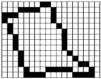
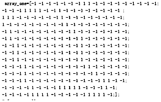
The invention relates to a reciprocating type compressor indicator diagram testing device and a fault diagnosis method, and belongs to the technical field of error diagnosis of a reciprocating type compressor. According to the reciprocating type compressor indicator diagram testing device and the fault diagnosis method disclosed by the invention, an indicator diagram of the reciprocating type compressor is identified by adopting discrete type Hopfield nerve network, and meanwhile, an associative memory function of the discrete type Hopfield nerve network is utilized, so that the indicator diagram of the reciprocating type compressor is accurately measured and identified by utilizing the function, and a satisfactory effect is achieved; and moreover, the calculation convergence speed is high.

Description

technical field [0001] The invention relates to a reciprocating compressor indicator diagram testing device and a fault diagnosis method, and relates to the technical field of reciprocating compressor fault diagnosis. Background technique [0002] The indicator diagram of a reciprocating compressor is a graph reflecting the gas pressure change in the cylinder of the compressor during a working cycle. The test of the indicator diagram is one of the basic methods to study the performance and working status of the compressor; using the indicator diagram The average that can be calculated is only the pressure, indicated power, actual pressure ratio and volume coefficient; at the same time, according to the shape of the construction drawing, the leakage of the valve, piston ring, packing, etc., and the pressure loss during the intake and exhaust process can be analyzed and judged. ; heat exchange in the process of compression and expansion, etc.; so that the fault diagnosis of th...

Claims


Application Information

Patent Timeline
IPC IPC(8): F04B51/00
Inventor 周元华朱植宇易先中
Owner YANGTZE UNIVERSITY
Why Eureka
Try Eureka