Reticulated-shell-structure-based model experimental device
A technology of structural models and experimental devices, which is applied in the direction of measuring devices, testing of machines/structural components, instruments, etc., can solve problems such as inability to model earthquake resistance, load capacity experiments, inability to simulate directional seismic waves, and long experimental procedures. To achieve the effect of simple structure, diverse functions and easy operation
- Summary
- Abstract
- Description
- Claims
- Application Information
AI Technical Summary
Problems solved by technology
Method used
Image
Examples
Embodiment 1
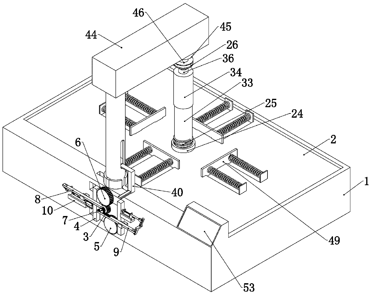
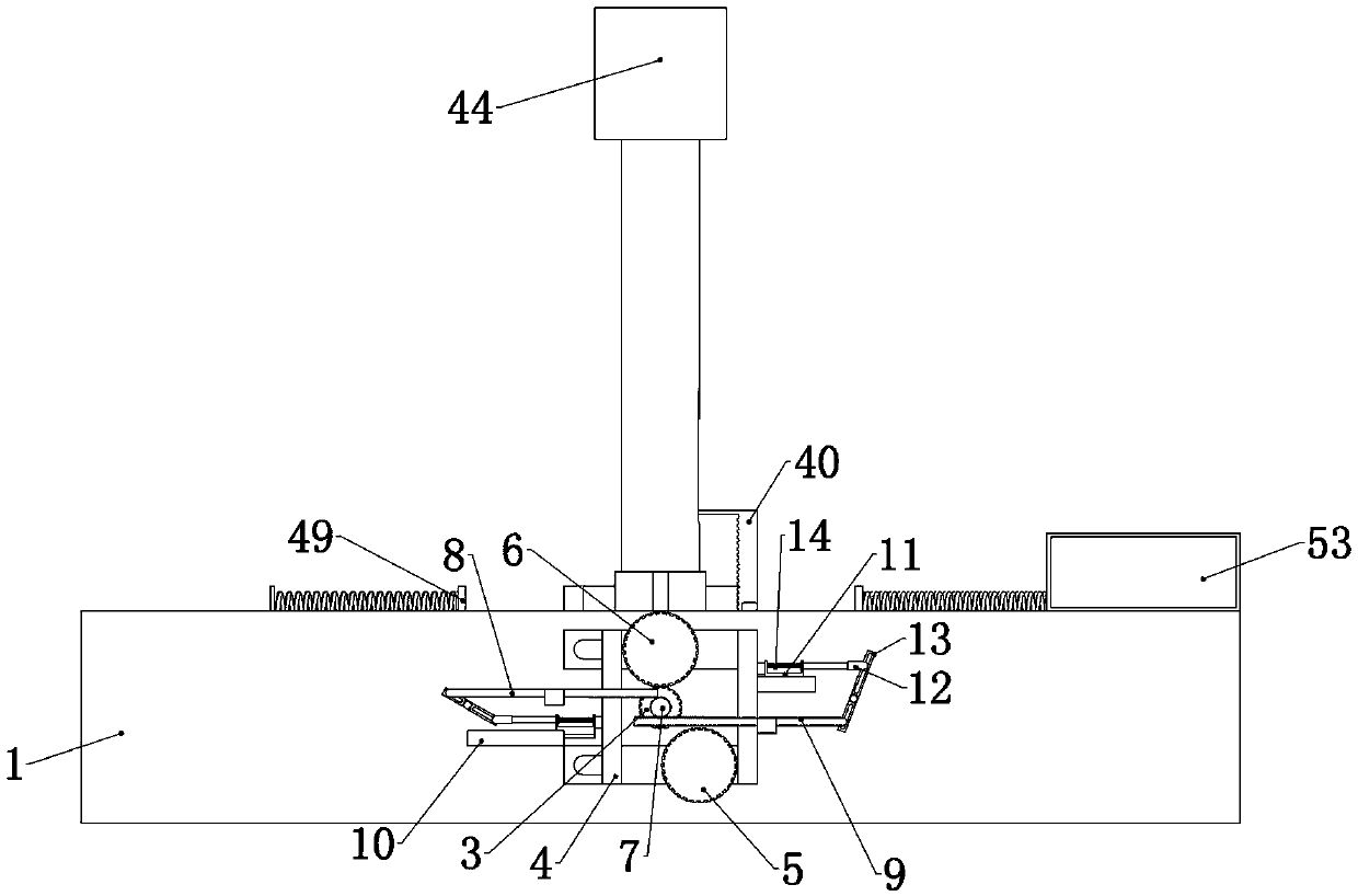
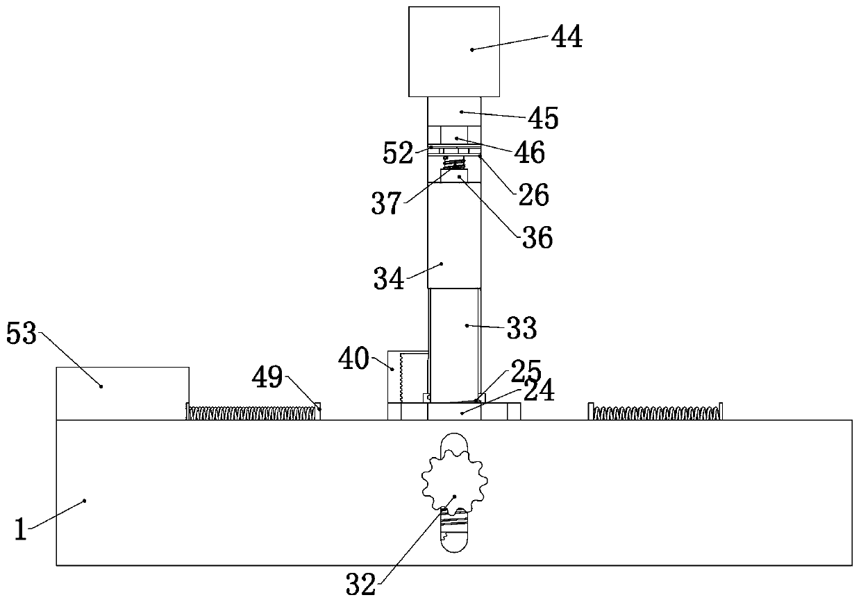
[0045] Embodiment 1, the present invention is a reticulated shell structure model experimental device, which includes a hollow shell 1 without a roof. The shell 1 can be placed on the table or the ground to provide a fixed foundation for the subsequent structure, and at the same time, it can be placed outside the shell 1. The end face is fixedly connected to the rubber legs, which increases the stability of the shell 1 placed on the desktop, and at the same time prevents the overall displacement of the device due to vibration when the device is doing an anti-seismic experiment. It is characterized in that the inside of the shell 1 slides up and down. The loading plate 2, the loading plate 2 is used to carry the reticulated shell structure model, the clamping device is provided on the loading plate 2, and the clamping device is used to hold the mesh on the loading plate 2 The shell structure model is firmly fixed on the loading plate 2 to prevent its displacement during the vibr...
Embodiment 2
[0047] Embodiment 2, on the basis of Embodiment 1, this embodiment provides a specific structure of the adjustment device, so that the upper adjustment rack 8 or the lower adjustment rack 9 does not work in the process of sliding to the left or right, Only when the upper adjustment rack 8 or the lower adjustment rack 9 is out of mesh with the adjustment drive gear 7, the corresponding adjustment device will work and push the gear frame 4 to slide in the corresponding direction. Specifically, refer to Figure 4 , Figure 5 , Image 6 , Figure 7, the two adjustment devices are respectively placed at the left and right ends of the gear frame 4, and the two adjustment devices all include an adjustment slide rail 10 fixedly connected to the front end of the housing 1, and the two adjustment slide rails 10 is slidingly connected to the left and right to adjust the U-shaped slide block 11, and the described adjustment slide rail 10 can be any common type of slide rail. While slid...
Embodiment 3
[0048] Embodiment 3, on the basis of Embodiment 1, this embodiment provides a specific vibration device, so that when the lower driven helical gear 5 and the driving helical gear 3 mesh, the driving helical gear 3 can rotate through the lower driven helical gear 5 Drive the vibrating device to work, thereby driving the carrier plate 2 to vibrate, and making the manufacturing place of the vibrating device have directional shock waves. Specifically, refer to Figure 8 , Figure 9 , Figure 10 , the vibration device includes a vibration driving gear 16 that is coaxially and fixedly connected with the lower driven helical gear 5 and is rotatably connected to the inside of the housing 1. The front end of the housing 1 is rotatably connected to a vibration idler 17, and the gear frame 4 When the driven helical gear 5 and the driving helical gear 3 are meshed with the left movement, the vibration driving gear 16 moves synchronously and meshes with the vibration idler gear 17. The vi...
PUM
 Abstract
Description
Claims
Application Information
 - R&D
- Intellectual Property
- Life Sciences
- Materials
- Tech Scout
- Unparalleled Data Quality
- Higher Quality Content
- 60% Fewer Hallucinations
Browse by: Latest US Patents, China's latest patents, Technical Efficacy Thesaurus, Application Domain, Technology Topic, Popular Technical Reports.
© 2025 PatSnap. All rights reserved.Legal|Privacy policy|Modern Slavery Act Transparency Statement|Sitemap|About US| Contact US: help@patsnap.com


