A Lever-Based Slow Tensile Stress Corrosion Experimental Device

A tensile stress and corrosion test technology, applied in measuring devices, weather resistance/light resistance/corrosion resistance, using stable tension/pressure to test the strength of materials, etc. Not tight enough, etc., to achieve the effect of accurate measurement, simple device and strong applicability

Active Publication Date: 2021-06-01
NANJING INST OF TECH
View PDF6 Cites 0 Cited by
  • Summary
  • Abstract
  • Description
  • Claims
  • Application Information

AI Technical Summary

Problems solved by technology

[0003] Most of the existing lever structure creep testing machines do not consider the constant force fluctuation caused by the change of the force direction caused by the moment the lever is tilted after the sample is stretched, and most of the commonly used leveling devices are handwheel adjustments with low accuracy , and few creep testing machines use experimental devices that combine creep stress and corrosive environment, and the applicability of materials in special engineering environments is different.
In the existing patent "a lever-type creep testing machine", its disadvantage is that when the lever is out of balance, it can be leveled by adjusting the height. During the leveling process, the constant force cannot be maintained, and there is no protection against the tensile fracture of the sample. Protection measures, the performance is relatively simple
"A mechanical high-temperature creep testing machine that can realize automatic and accurate loading", its disadvantage is that there is no measure to control the direction during the leveling process, the magnitude of the applied force is affected, and the range of applicable environments is relatively limited
"Interleaving corrosion test method and device based on slow tensile stress corrosion testing machine", its disadvantage is that it focuses more on electrochemical corrosion experimental methods, and the combination with slow tensile is not close enough, and its practicability is not perfect.

Method used


Image

  • A Lever-Based Slow Tensile Stress Corrosion Experimental Device
  • A Lever-Based Slow Tensile Stress Corrosion Experimental Device
  • A Lever-Based Slow Tensile Stress Corrosion Experimental Device

Examples


Embodiment Construction

[0020] In order to make the technical means, creative features, goals and effects achieved by the present invention easy to understand, the present invention will be further described below in conjunction with specific embodiments.

[0021] It should be noted that, in the description of the present invention, the terms "front", "rear", "left", "right", "upper", "lower", "inner", "outer" and the like indicate orientations or positions The relationship is based on the orientation or positional relationship shown in the drawings, and is only for the convenience of describing the present invention and does not require that the present invention must be constructed and operated in a specific orientation, and thus should not be construed as a limitation of the present invention. The terms "front", "rear", "left", "right", "upper" and "lower" used in the description of the present invention refer to the directions in the drawings, and the terms "inner" and "outer" refer to is the dir...


PUM


Abstract

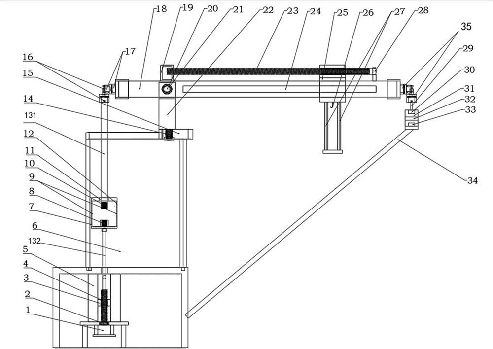
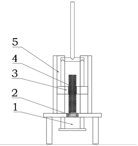
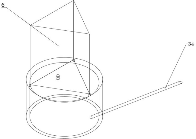
The invention discloses a slow tensile stress corrosion experiment device based on a lever, which includes a lever balance system, a corrosion test system and a feedback adjustment system; the lever balance system includes a lever and a lever bracket for supporting the lever, and the left end of the lever is connected with a The test system has a weight device at the right end of the lever; the corrosion test system includes an electrochemical corrosion cylinder, which is used to simulate the corrosion environment and fix the sample, and the electrochemical corrosion cylinder is connected to the left end of the lever; the feedback adjustment system is connected to Between the lever balance system and the corrosion test system, the feedback adjustment system is used to adjust the balance of the lever; the present invention can amplify the load of the weight through the lever structure, reduce the additional stress on the rod, load different loads or move the weight before the experiment The location can provide a variety of creep stress and tension conditions. The device is simple and accurate in measurement, and it is easy to realize real-time monitoring of creep stress and displacement under constant force.

Description

technical field [0001] The invention relates to the technical field of detection equipment, in particular to a lever-based slow tensile stress corrosion test device. Background technique [0002] Creep refers to the phenomenon that the strain of a solid material increases with time under the condition of keeping the stress constant. Mechanical creep testing machines are often used to determine the creep durability of metals. Most of the existing creep testing machines use lever loading, and the old lever creep testing machines mostly use artificial loading weights to apply tension. For The control accuracy of the constant force is low, and the error of the measured experimental data is relatively large. [0003] Most of the existing lever structure creep testing machines do not consider the constant force fluctuation caused by the change of the force direction caused by the moment the lever is tilted after the sample is stretched, and most of the commonly used leveling devi...

Claims


Application Information

Patent Timeline
Patent Type & Authority Patents(China)
IPC IPC(8): G01N17/02G01N3/14
Inventor 张振余飞海李桂贞马颖涵廖海龙
Owner NANJING INST OF TECH
Why Eureka
Try Eureka