
A phase change state detection device under high pressure

A state detection device and phase change technology, applied in the direction of transmittance measurement, etc., can solve problems such as neglect and inability to apply high-voltage detection scenarios, and achieve a stable and reliable structure

Active Publication Date: 2021-08-10
余姚市浙江大学机器人研究中心 +1
View PDF7 Cites 0 Cited by
  • Summary
  • Abstract
  • Description
  • Claims
  • Application Information

AI Technical Summary

Problems solved by technology

The above methods measure the phase change of the material through the acoustic wave propagation characteristics and the change of the material resistivity respectively, but there is a problem in these methods: they only work normally under standard atmospheric pressure, so they can only detect the phase change and temperature of the material under normal pressure. relationship, which cannot be applied to high-voltage detection scenarios, ignoring the high-voltage factor

Method used


Image

  • A phase change state detection device under high pressure
  • A phase change state detection device under high pressure

Examples


Embodiment Construction

[0020] The present invention will be further described below in conjunction with accompanying drawing:

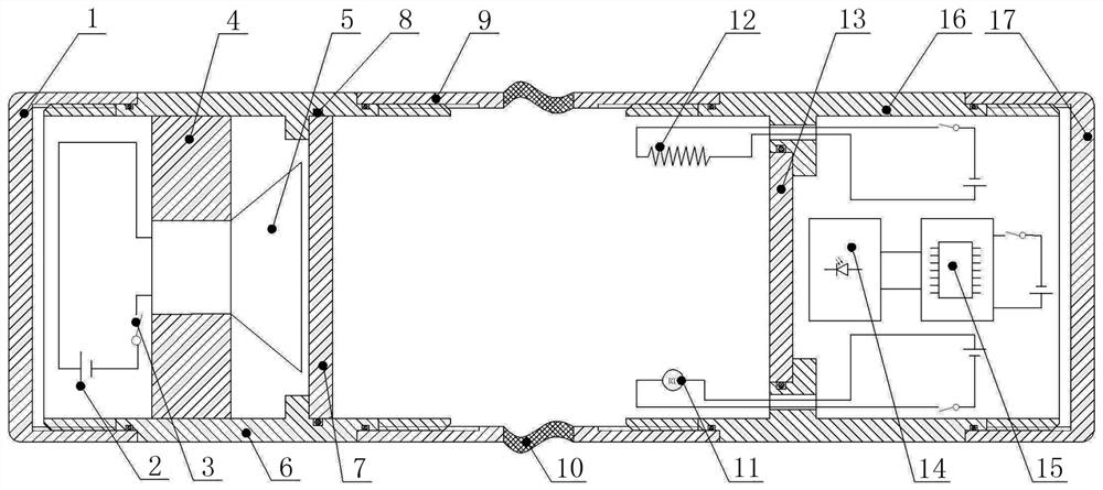
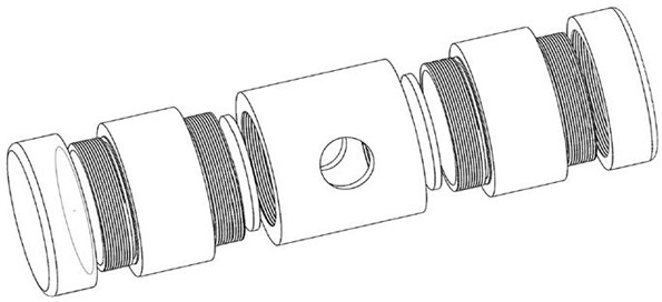
[0021] Such as Figure 1-2 As shown, a phase change state detection device under high pressure includes a light source bin, a material bin and a photoelectric detection and temperature control unit. The left side of the material bin is provided with a light source bin, and the right side of the material bin is provided with a photoelectric detection and a temperature control unit, the light source chamber is composed of a left end cover 1, a DC power supply 2, a switch 3, a light source bracket 4, a laser 5, a first high-voltage resistant shell 6 and a first light-transmitting plate 7, and the first high-voltage resistant The left end of the casing 6 is provided with a left end cover 1, and the first high-voltage resistant casing 6 is connected with the left end cover 1 through threads. A laser 5 is fixed on it, and the laser 5 is connected with a DC power supply 2 and a s...


PUM

PropertyMeasurementUnit
transmittivityaaaaaaaaaa

Abstract

The invention discloses a device for detecting phase transition of materials under high pressure. The device consists of three parts: light source bin, material bin, photoelectric detection and temperature control unit. When the device is working, it is placed in a pressure regulating container, and the external pressure is transmitted to the material to be tested in the material bin through the soft bag. The temperature in the material bin is regulated by the internal temperature control unit. When the device is working, the light source produces parallel light rays, which illuminate the material to be tested in the material bin vertically, and the light transmittance of the material under different pressures and temperatures is measured by the photoelectric detection unit. The data analysis and processing of the light transmittance signal can obtain the continuous phase transition state of the material under different pressures and temperatures. The device provides effective data support for the selection of phase-change buoyancy materials.

Description

technical field [0001] The invention relates to the field of material phase change detection, in particular to a phase change state detection device under high pressure. Background technique [0002] The process of a substance changing from one phase to another is called a phase transition. A phase change changes the volume of an object. Temperature and pressure are the two major influencing factors of phase transition. When the temperature is constant, the pressure will affect the melting point and boiling point of the material, thus affecting the phase transition of the material. [0003] At present, there are ultrasonic detection methods, electrical (resistance) detection methods, etc. for material phase change detection methods. The above methods measure the phase change of materials through the acoustic wave propagation characteristics and the change of material resistivity respectively, but there is a problem in these methods: they only work normally under standard ...

Claims


Application Information

Patent Timeline
Patent Type & Authority Patents(China)
IPC IPC(8): G01N21/59
Inventor 宋伟王程汪志坚张訸
Owner 余姚市浙江大学机器人研究中心
Learn More