A cable tensile connection structure and a load-bearing watertight connector using the structure

A connection structure and connector technology, which is applied to the device for relieving the stress of the wire connection, the parts of the connection device, the connection, etc., can solve the problems of reducing connection reliability, affecting signal transmission, and failure, and can improve waterproof performance Effect

Active Publication Date: 2020-10-13
GUIZHOU SPACE APPLIANCE CO LTD
View PDF30 Cites 0 Cited by
  • Summary
  • Abstract
  • Description
  • Claims
  • Application Information

AI Technical Summary

Problems solved by technology

[0002] At present, with the promotion and implementation of the national marine strategy, there is a strong demand for various underwater electromechanical equipment. In the fields of hanging sonar systems, hanging underwater camera systems, etc., tensile joints have become commonly used connecting devices, such as the publication number CN2849326Y The patent discloses a tension-resistant joint, which is used to connect the ends of cables, steel wire ropes or fiber ropes. The shape of the tapered core is adapted to the inner cavity of the tapered sleeve. Although the transmission of the photoelectric signal is guaranteed, it is subject to constant waves. When working, the load-bearing cable will shake, and there is no special waterproof design, it is very likely to malfunction and affect signal transmission, and the patent with the publication number of CN104183972A discloses a tensile connection structure of the cable and the use of the tensile connection The connector of the structure also uses the integral taper sleeve connection method to connect and fix the cables. Its main feature is to improve the installation efficiency of the cable tensile connection, but it will also greatly reduce the connection when used in a watertight environment. reliability

Method used


Image

  • A cable tensile connection structure and a load-bearing watertight connector using the structure
  • A cable tensile connection structure and a load-bearing watertight connector using the structure
  • A cable tensile connection structure and a load-bearing watertight connector using the structure

Examples


Embodiment Construction

[0035] The technical solution of the present invention is further described below, but the scope of protection is not limited to the description.

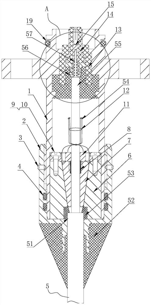
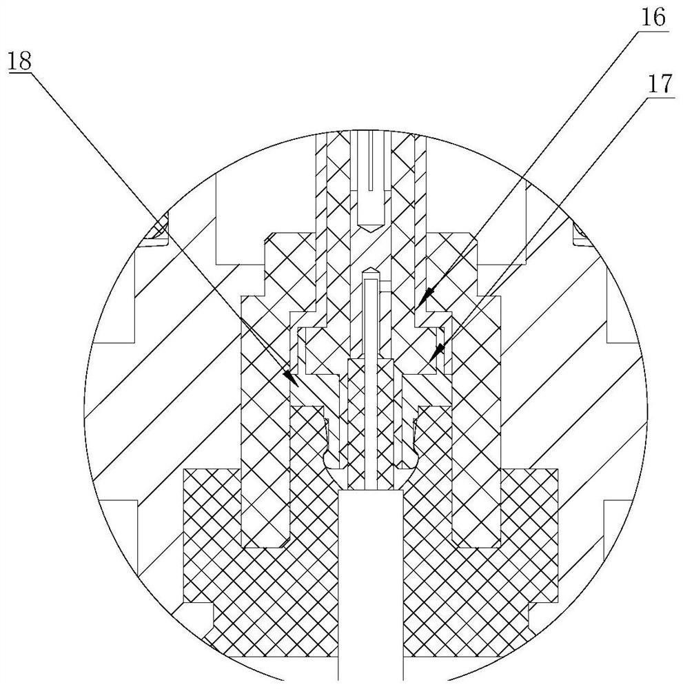
[0036] as attached Figure 1-2 As shown, a cable tensile connection structure mainly includes an intermediate sleeve 6, a central sleeve 7, mounting screws 9, spring washers 10 and a pressure plate 11,

[0037] Both sides of the outer circular surface of the intermediate sleeve 6 are provided with anti-rotation flats, and the front end surface is provided with threaded holes uniformly distributed in the circumferential direction for the connection of the pressure plate and through holes for injecting glue. The inner hole is composed of a tapered hole connected with a cylindrical hole. Among them, the tapered hole is located at the front end, and the cylindrical hole is located at the rear end;

[0038] The outside of the central sleeve 7 is tapered, the size is adapted to the inner hole of the intermediate sleeve 6, and inserted i...


PUM


Abstract

A cable tensile connection structure and a load-bearing watertight connector using the structure, the cable tensile connection structure mainly includes an intermediate sleeve, a central sleeve, mounting screws, spring washers and a pressure plate, and the load-bearing watertight connector includes In addition to the tensile connection structure, it also includes a shell, a tail sleeve, a set screw with a tapered end, a first sealing ring, a central conductor, and an intermediate conductor assembly. Through the implementation of the present invention, a load-bearing coaxial cable with a load-bearing rope and a sealed protective layer added outside the coaxial wire is used, and the load-bearing cable is used to connect the water extension to the underwater extension, and the water extension can be connected through a single cable. Realize the direct energy supply and control of the underwater extension, and at the same time, a special waterproof structure is set on the connector, and most of the key components are connected by screw connection and interference fit, which greatly improves the waterproof of the connector performance.

Description

technical field [0001] The invention belongs to the technical field of machinery, and in particular relates to a cable tensile connection structure and a load-bearing watertight connector using the structure. Background technique [0002] At present, with the promotion and implementation of the national marine strategy, there is a strong demand for various underwater electromechanical equipment. In the fields of hanging sonar systems, hanging underwater camera systems, etc., tensile joints have become commonly used connecting devices, such as the publication number CN2849326Y The patent discloses a tension-resistant joint, which is used to connect the ends of cables, steel wire ropes or fiber ropes. The shape of the tapered core is adapted to the inner cavity of the tapered sleeve. Although the transmission of the photoelectric signal is guaranteed, it is subject to constant waves. When working, the load-bearing cable will shake, and there is no special waterproof design, it...

Claims


Application Information

Patent Timeline
Patent Type & Authority Patents(China)
IPC IPC(8): H01R13/502H01R13/512H01R13/52H01R13/58H01R24/00
CPCH01R13/502H01R13/512H01R13/52H01R13/5202H01R13/5205H01R13/5812H01R24/00
Inventor 周山鹏刘贲郭进
Owner GUIZHOU SPACE APPLIANCE CO LTD
Why Eureka
Try Eureka