Safety protection power cabinet
A technology for safety protection and power cabinets, which is applied in the direction of substation/power distribution device shells, etc., and can solve problems such as inability to protect power cabinets
- Summary
- Abstract
- Description
- Claims
- Application Information
AI Technical Summary
Problems solved by technology
Method used
Image

Examples
specific Embodiment approach 1
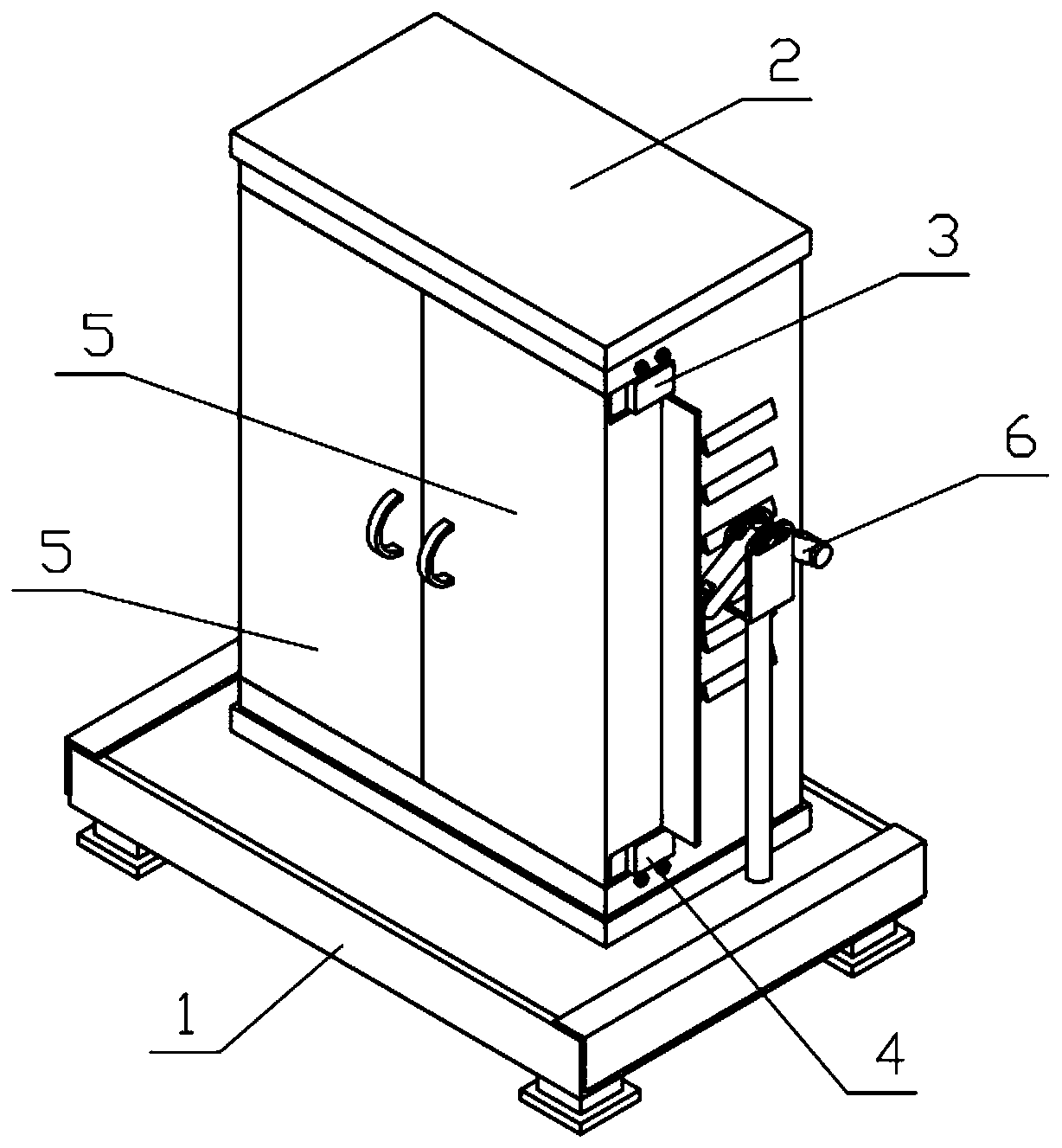
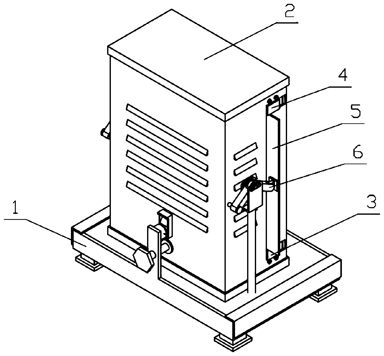
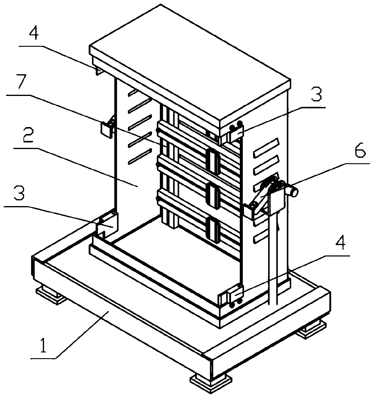
[0030] Combine below Figure 1-12Describe this embodiment, a safety protection power cabinet, including a support mechanism 1, a power cabinet 2, an installation mechanism I3, an installation mechanism II4, a power cabinet door 5, a linkage mechanism 6, and an electrical installation frame 7. The support mechanism 1 and A compression spring I is arranged between the power cabinets 2, and the power cabinet 2 is installed on the support mechanism 1. Two installation mechanisms I3 and two installation mechanisms II4 are fixedly connected to the power cabinet 2, and the installation mechanism I3 and the installation mechanism II4 on both sides The power cabinet door 5 is connected to each other in rotation, and two linkage mechanisms 6 are provided. One end of the two linkage mechanisms 6 is hinged on the power cabinet 2, and the middle ends of the two linkage mechanisms 6 are hinged on the support mechanism. 1, the other ends of the two linkage mechanisms 6 are pushed against the...
specific Embodiment approach 2
[0031] Combine below Figure 1-12 Describe this embodiment, this embodiment will further explain the first embodiment, the support mechanism 1 includes a support base plate 1-1, a support sliding cylinder 1-2, a limit baffle I1-3, a closing sliding column 1-4, a connecting Plate 1-5, block support cylinder 1-6, triangular block 1-7 and positioning threaded rod 1-8, support base plate 1-1 is a box body with an open upper end, on the four corners of support base plate 1-1 Both sides are fixedly connected with a supporting sliding cylinder 1-2, both sides of the supporting bottom plate 1-1 are fixedly connected with the limit baffle Ⅰ1-3, and the supporting bottom plate 1-1 is fixedly connected with two closed sliding columns 1-4, the supporting bottom plate The rear side of 1-1 is fixedly connected with a connecting plate 1-5, the connecting plate 1-5 is fixedly connected with a block support cylinder 1-6, the triangular block 1-7 is fixedly connected with a sliding column, and ...
specific Embodiment approach 3
[0032] Combine below Figure 1-12 Describe this embodiment, this embodiment will further explain the second embodiment, the power cabinet 2 includes the power cabinet bottom plate 2-1, the power cabinet body 2-2, the ventilation hole I2-3, the ventilation hole II2-4, the power cabinet Top plate 2-5, hinged column I 2-6, supporting sliding column 2-7 and W clamping block 2-8, the upper end of the power cabinet bottom plate 2-1 is fixedly connected with the power cabinet body 2-2, and the power cabinet body 2-2 The left and right sides of the cabinet are fixedly connected with hinge columns I2-6, the left and right sides of the power cabinet body 2-2 are provided with ventilation holes I2-3, and the rear side of the power cabinet body 2-2 is provided with ventilation holes II2-4, The upper end of the power cabinet body 2-2 is fixedly connected with a power cabinet top plate 2-5, and the four corners of the lower end of the power cabinet bottom plate 2-1 are fixedly connected wit...
PUM
 Abstract
Description
Claims
Application Information
 - R&D Engineer
- R&D Manager
- IP Professional
- Industry Leading Data Capabilities
- Powerful AI technology
- Patent DNA Extraction
Browse by: Latest US Patents, China's latest patents, Technical Efficacy Thesaurus, Application Domain, Technology Topic.
© 2024 PatSnap. All rights reserved.Legal|Privacy policy|Modern Slavery Act Transparency Statement|Sitemap