Combined standby power switch-in method based on hot standby line

A standby power supply and hot standby technology, which is applied in the direction of emergency power supply arrangement, electrical components, circuit devices, etc., can solve the problems of power grid reactive power transfer and high capacitive substation

Inactive Publication Date: 2019-05-31
STATE GRID JIANGSU ELECTRIC POWER CO ZHENJIANG POWER SUPPLY CO
View PDF4 Cites 2 Cited by
  • Summary
  • Abstract
  • Description
  • Claims
  • Application Information

AI Technical Summary

Problems solved by technology

[0004] The purpose of the present invention is to provide a combined backup power supply input method based on hot standby lines to solve the problems of excessive capacitive reactive power in most substations and reactive power reversed in power grids

Method used


Image

  • Combined standby power switch-in method based on hot standby line
  • Combined standby power switch-in method based on hot standby line
  • Combined standby power switch-in method based on hot standby line

Examples


Embodiment Construction

[0196] The present invention will be further described below in conjunction with the accompanying drawings and specific embodiments.

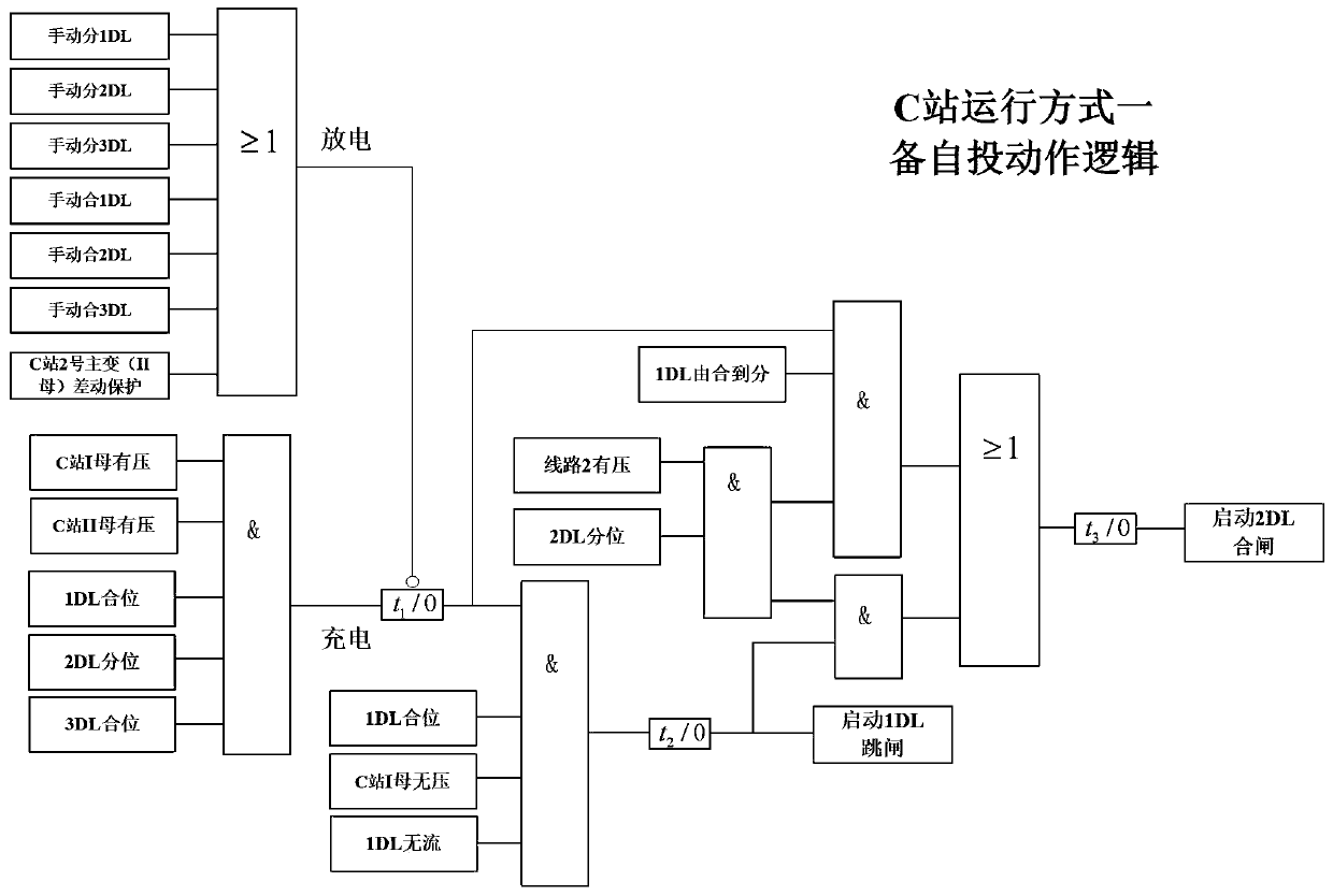
[0197] Such as image 3 , 4 As shown, station C in the present invention satisfies the following main connection:

[0198] (1) Primary main wiring of 110kV inner bridge in 110kV substation;

[0199] (2) 110kV single busbar subsection primary main wiring in 110kV substation.

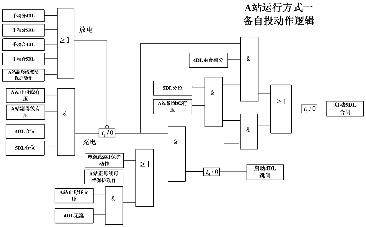
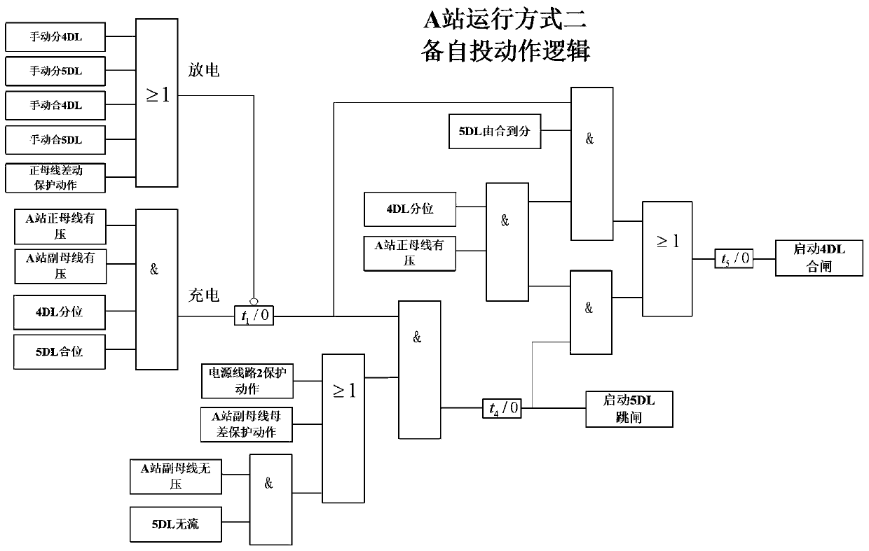
[0200] The power transmission and distribution network applied by the method of the present invention is two 110kV lines, a 220kV substation A and a 110kV substation C, including:

[0201] (1) 110kV line 1 and 110kV line 2 both come from the same substation A; (2) 110kV line 1 is respectively connected to the 110kV main busbar of 220kVA station and the busbar of section I of 110kV station C, and the fourth circuit breaker 4DL, Current transformer CT4, first circuit breaker 1DL and current transformer CT1 on the load side of line 1; (3) 110kV line 2 is respectively conne...


PUM


Abstract

The invention discloses a combined standby power switch-in method based on a hot standby line. The method is applied to the 110kV inner bridge primary main line of an 110kV substation or the110kV single bus section primary main line of the 110kV substation. The method solves the problem of substation over-high capacitive reactive power and grid reactive power backflow, improves the substation voltage level, avoids over-high local grid voltage, improves the overall operation level of the grid, reduces equipment loss and insulation aging, improves the operating efficiency of the substation mainequipment, increases a substation power factor, improves the economical operation of the grid, avoids the large-scale power outage accidents when the main supply line is permanently faulty, realizes self-healing of the grid, and improves the reliability of power supply. The method can be used as a technical guarantee for the special operation mode of the grid, greatly improves the safety risk management and control under the special operation mode, and promotes the safe and stable operation of the grid.

Description

technical field [0001] The invention relates to a combined standby power input method based on a hot standby line, and belongs to the technical field of electric power transmission and distribution control. Background technique [0002] With the promotion of urban construction and the improvement of power grid structure, the high and low voltage sides of 110kV and below substations are generally powered by cable lines, resulting in increasing capacitive reactive power. On the one hand, most urban substations lack reactors due to the long operation time and the saturated number of intervals, so they cannot absorb excess capacitive reactive power; etc. are restricted by internal and external factors and cannot operate. What is more serious is that the phenomenon of reactive power transfer in the power grid during low load periods during holidays is common, resulting in a significant decrease in power factor and high voltage in some areas of the power grid (grid operation show...

Claims


Application Information

Patent Timeline
Patent Type & Authority Applications(China)
IPC IPC(8): H02J9/06
CPCY02B70/30Y04S20/20
Inventor 马骏毅任萱张大林施伟成汤大海杜炜凝马海薇巴宇李静许象明
Owner STATE GRID JIANGSU ELECTRIC POWER CO ZHENJIANG POWER SUPPLY CO
Why Eureka
Try Eureka