

Forming mold for automobile exhaust pipe
A technology for automobile exhaust and forming molds, which is applied in the field of mold equipment, can solve the problems of slow cooling rate, low efficiency, and lack of monitoring performance of connection tightness, etc., and achieve the effect of improving precision
- Summary
- Abstract
- Description
- Claims
- Application Information
AI Technical Summary
Problems solved by technology
Method used
Image

Examples
Embodiment 1
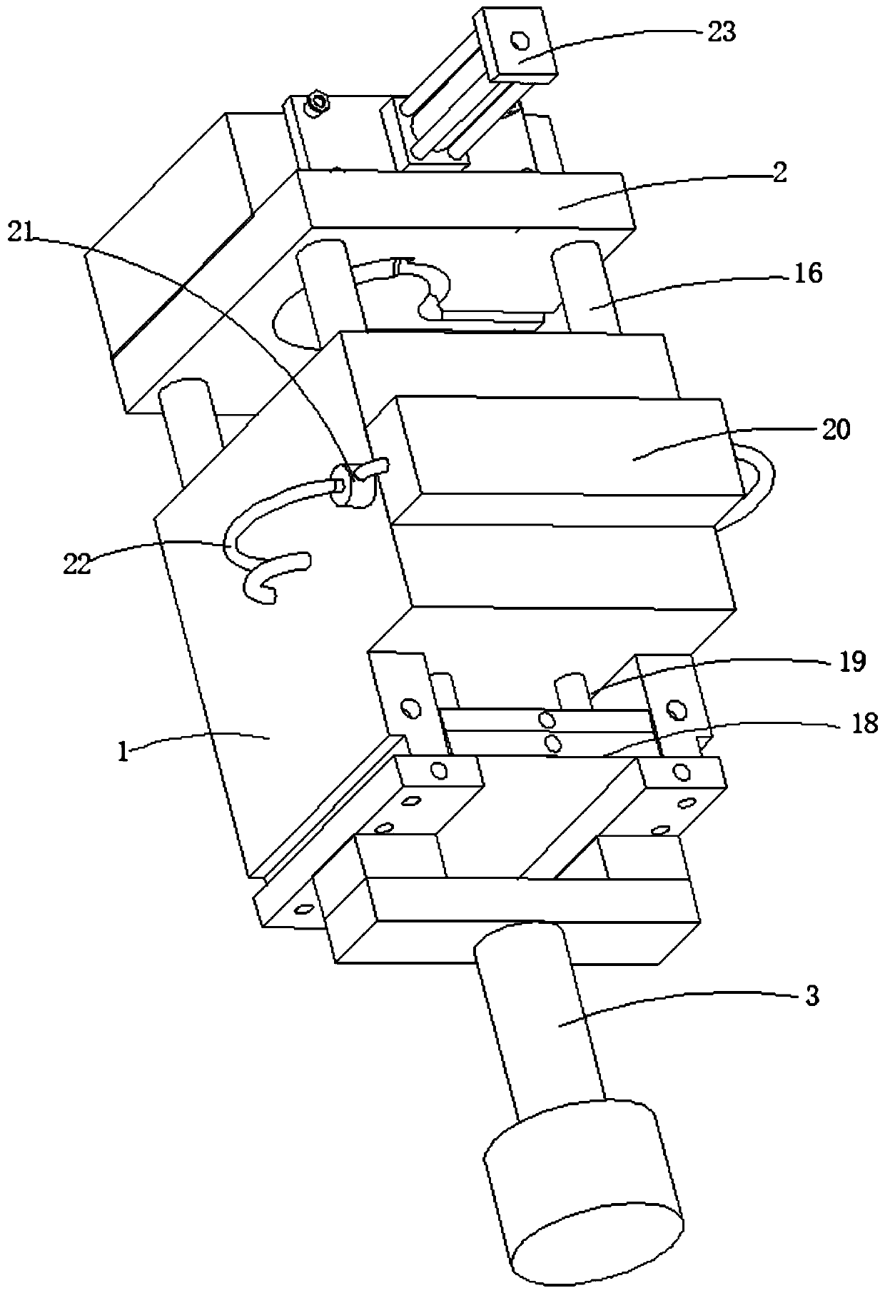
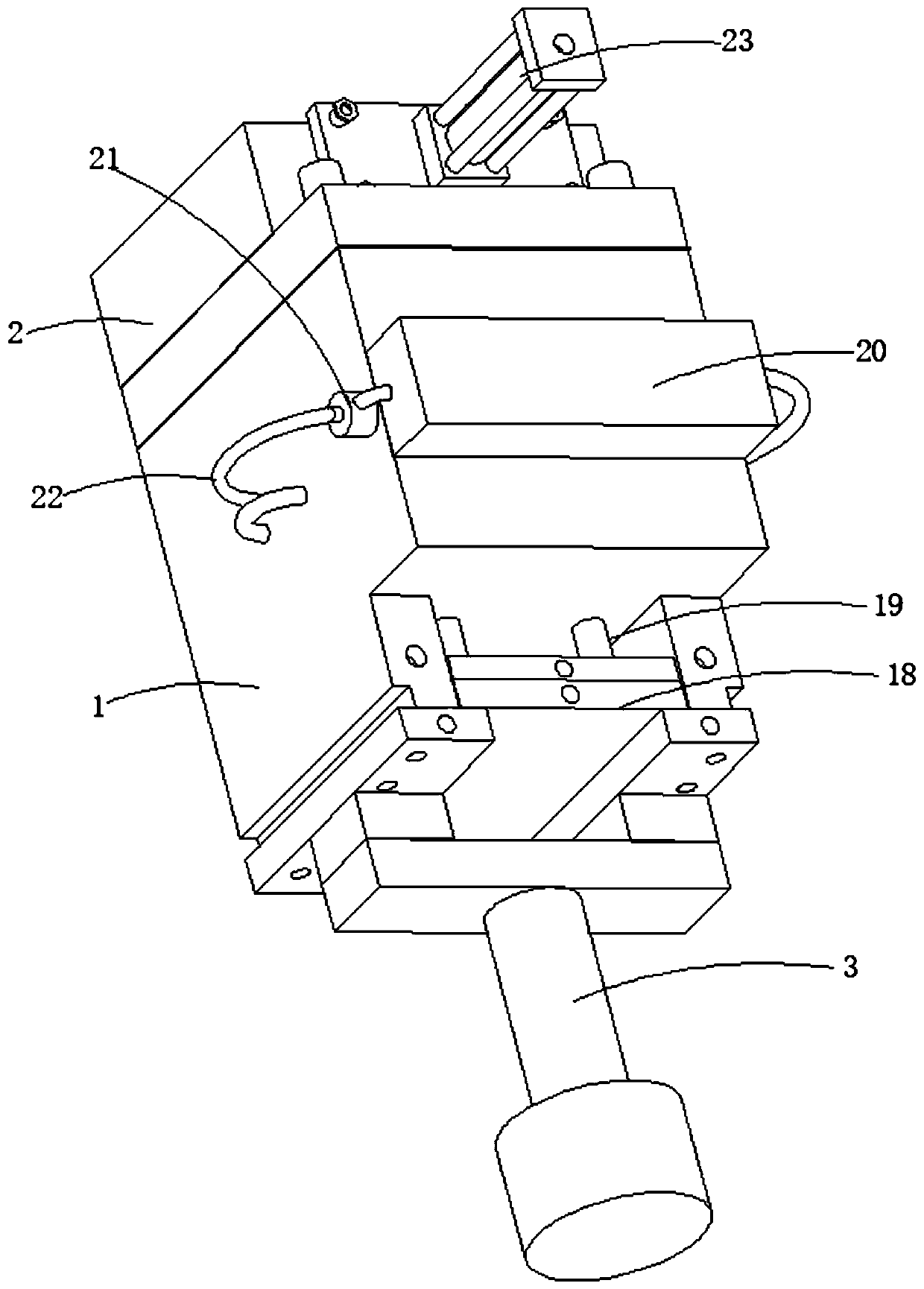
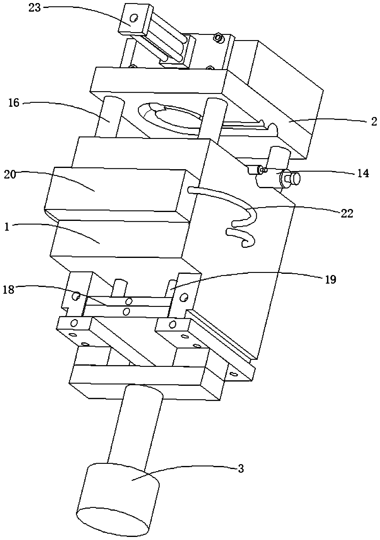
[0038]refer to Figure 1-11 , a molding die for an automobile exhaust pipe, comprising a moving die set 1, a fixed die set 2, a moving die cavity, a fixed die cavity, a shooting oil cylinder 3, a pushing mechanism and a cooling system, the moving die cavity and the fixed die cavity Both are provided with a core bend pipe part 4 and a core straight pipe part 5, and a straight pipe groove 6 and a pipe bend groove 7 communicating with the movable mold cavity and the fixed mold cavity are excavated on the movable die set 1 and the fixed die set 2, The opposite ends of the core curved pipe part 4 and the core straight pipe part 5 are opposed to each other, and the ends of the core curved pipe part 4 and the core straight pipe part 5 that are far away from each other are slidably connected in the curved pipe groove 7 and the straight pipe groove 6 respectively. Cooling grooves 8 are excavated on the bent pipe part 4 of the core and the straight pipe part 5 of the core. The pipe 10 ...
Embodiment 2
[0048] refer to Figure 1-12 , a molding die for an automobile exhaust pipe, a molding die for an automobile exhaust pipe, comprising a moving die set 1, a fixed die set 2, a moving die cavity, a fixed die cavity, a shooting oil cylinder 3, a pushing mechanism and a cooling system, both the movable mold cavity and the fixed mold cavity are provided with a core bend pipe part 4 and a core straight pipe part 5, and the movable mold group 1 and the fixed mold group 2 are also excavated to communicate with the movable mold cavity and the fixed mold cavity. The straight pipe groove 6 and the curved pipe groove 7, the opposite ends of the core curved pipe part 4 and the core straight pipe part 5 are against each other, and the ends of the core curved pipe part 4 and the core straight pipe part 5 are respectively slidably connected to the curved pipe part 4 and the core straight pipe part 5. In the pipe groove 7 and the straight pipe groove 6, cooling grooves 8 are excavated on the c...
PUM
 Abstract
Description
Claims
Application Information