A double-station fixture for CNC milling machine

A CNC milling machine, double-station technology, applied in the direction of manufacturing tools, clamping, positioning devices, etc., can solve the problems of time-consuming, labor-intensive, low work efficiency, etc.

Active Publication Date: 2020-11-13
河北维普机床制造有限公司
View PDF10 Cites 0 Cited by
  • Summary
  • Abstract
  • Description
  • Claims
  • Application Information

AI Technical Summary

Problems solved by technology

[0003] In order to overcome the disadvantages that the existing clamps for CNC milling machines can only clamp a single workpiece, after the workpiece is processed, it is necessary to stop the machine to replace the workpiece, which is time-consuming and laborious, and the work efficiency is low. Therefore, the technical problem of the present invention is: to provide A time-saving, labor-saving and high-efficiency double-station fixture for CNC milling machines

Method used


Image

  • A double-station fixture for CNC milling machine
  • A double-station fixture for CNC milling machine
  • A double-station fixture for CNC milling machine

Examples


Embodiment 1

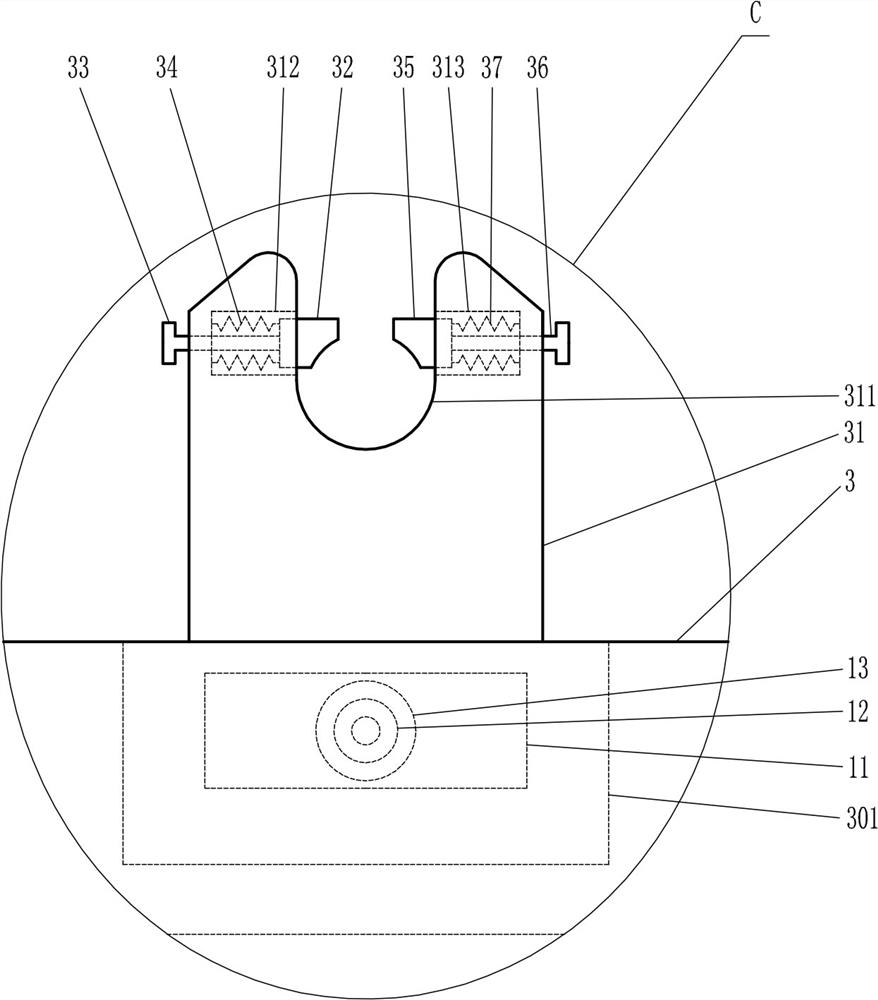
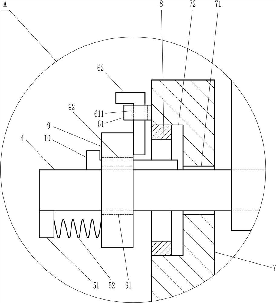
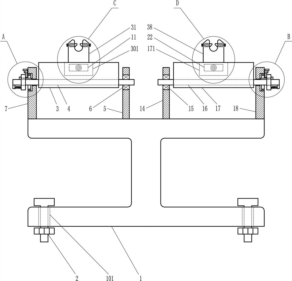
[0021] A double-station fixture for CNC milling machines, such as Figure 1-5 As shown, it includes an I-shaped base 1, a large bolt 2, a first tray 3, a first rotating shaft 4, a first support plate 5, a first bearing 6, a second support plate 7, a first inner ring gear 8, First gear plate 9, first L-shaped guide block 10, first pressure plate 11, second bearing 12, first long screw 13, third support plate 14, third bearing 15, second rotating shaft 16, second tray 17. The fourth support plate 18, the second ring gear 19, the second toothed plate 20, the second L-shaped guide block 21, the second pressure plate 22, the fourth bearing 23 and the second long screw 24, the I-shaped base 1 There is a large through hole 101 at the bottom of the bottom, the large bolt 2 is located in the large through hole 101, the I-shaped base 1 is in contact with the large bolt 2, the first tray 3 is located above the I-shaped base 1, and the lower fixing sleeve of the first tray 3 On the first...

Embodiment 2

[0023] A double-station fixture for CNC milling machines, such as Figure 1-5 As shown, it includes an I-shaped base 1, a large bolt 2, a first tray 3, a first rotating shaft 4, a first support plate 5, a first bearing 6, a second support plate 7, a first inner ring gear 8, First gear plate 9, first L-shaped guide block 10, first pressure plate 11, second bearing 12, first long screw 13, third support plate 14, third bearing 15, second rotating shaft 16, second tray 17. The fourth support plate 18, the second ring gear 19, the second toothed plate 20, the second L-shaped guide block 21, the second pressure plate 22, the fourth bearing 23 and the second long screw 24, the I-shaped base 1 There is a large through hole 101 at the bottom of the bottom, the large bolt 2 is located in the large through hole 101, the I-shaped base 1 is in contact with the large bolt 2, the first tray 3 is located above the I-shaped base 1, and the lower fixing sleeve of the first tray 3 On the first...

Embodiment 3

[0026] A double-station fixture for CNC milling machines, such as Figure 1-5 As shown, it includes an I-shaped base 1, a large bolt 2, a first tray 3, a first rotating shaft 4, a first support plate 5, a first bearing 6, a second support plate 7, a first inner ring gear 8, First gear plate 9, first L-shaped guide block 10, first pressure plate 11, second bearing 12, first long screw 13, third support plate 14, third bearing 15, second rotating shaft 16, second tray 17. The fourth support plate 18, the second ring gear 19, the second toothed plate 20, the second L-shaped guide block 21, the second pressure plate 22, the fourth bearing 23 and the second long screw 24, the I-shaped base 1 There is a large through hole 101 at the bottom of the bottom, the large bolt 2 is located in the large through hole 101, the I-shaped base 1 is in contact with the large bolt 2, the first tray 3 is located above the I-shaped base 1, and the lower fixing sleeve of the first tray 3 On the first...


PUM


Abstract

The invention relates to a clamp for a numerical control milling machine, in particular to a double-station clamp for a numerical control milling machine. Therefore, the double-station clamp for the numerical control milling machine is time-saving, labor-saving and high in working efficiency. According to the technical scheme, the double-station clamp for the numerical control milling machine comprises an I-shaped base, a large bolt, a first tray, a first rotating shaft, a first supporting plate, a first bearing and the like; a large through hole is formed in the bottom of the I-shaped base, the large bolt is located in the large through hole, the I-shaped base is in contact with the large bolt, the first tray is positioned above the I-shaped base, and the lower portion of the first tray fixedly sleeves the first rotating shaft. The double-station clamp for the numerical control milling machine can clamp a plurality of workpieces, the workpieces can be exchanged without shutdown, timeand labor are saved, the working efficiency is high, the workpieces can be obliquely processed, the clamping mode is diversified, and the structure is simple.

Description

technical field [0001] The invention relates to a fixture for a numerically controlled milling machine, in particular to a double-station fixture for a numerically controlled milling machine. Background technique [0002] CNC milling machine, also known as CNC, is an automatic processing equipment developed on the basis of general milling machines. The processing technology of the two is basically the same, and the structure is also somewhat similar. CNC milling machines are divided into two categories: without tool magazine and with tool magazine. Among them, the CNC milling machine with a tool magazine is also called a machining center. When using a CNC milling machine to process a workpiece, it is necessary to clamp the workpiece with a fixture. The existing fixture for a CNC milling machine can only clamp a single workpiece. , After the workpiece is processed, it needs to stop the machine to change the workpiece, which is time-consuming and laborious, and the work effici...

Claims


Application Information

Patent Timeline
Patent Type & Authority Patents(China)
IPC IPC(8): B23Q3/06B23Q3/04
Inventor 不公告发明人
Owner 河北维普机床制造有限公司
Why Eureka
Try Eureka