
Impeller pulling device making impeller to be overhauled and maintained simply and conveniently

A puller and impeller technology, which is applied in the field of impeller repair and maintenance, can solve problems such as inconvenient operation and deformation of the impeller, and achieve the effects of ensuring the integrity rate, reducing production costs, and shortening the time for repair

Inactive Publication Date: 2019-06-04
安武坤
View PDF0 Cites 0 Cited by
  • Summary
  • Abstract
  • Description
  • Claims
  • Application Information

AI Technical Summary

Problems solved by technology

[0004] The purpose of the present invention is to provide a puller that is easy to repair and maintain the impeller, so as to solve the technical problems of the prior art that the operation is inconvenient and the impeller is easily deformed when disassembling the impeller.

Method used


Image

  • Impeller pulling device making impeller to be overhauled and maintained simply and conveniently
  • Impeller pulling device making impeller to be overhauled and maintained simply and conveniently
  • Impeller pulling device making impeller to be overhauled and maintained simply and conveniently

Examples


Embodiment approach 1

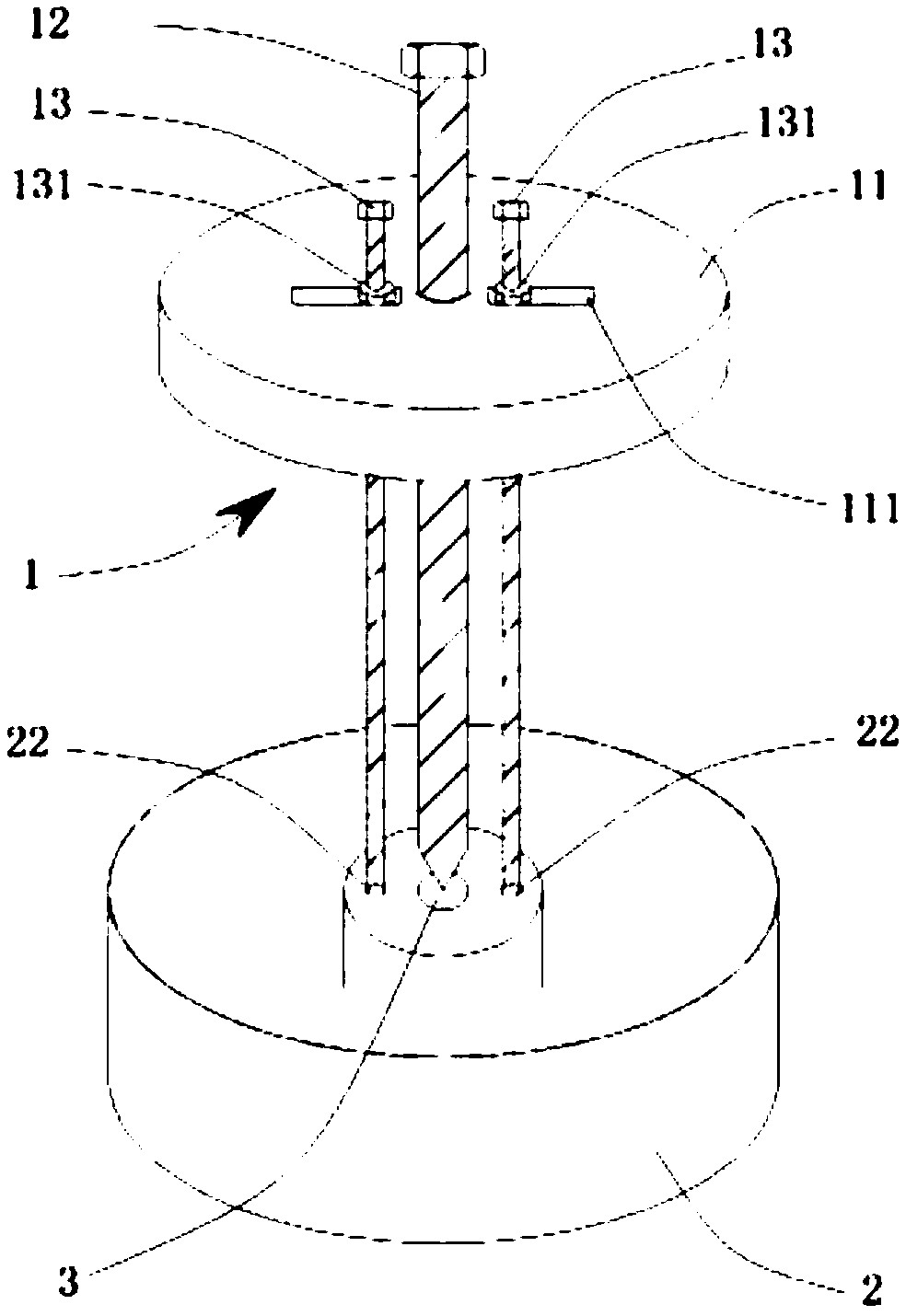
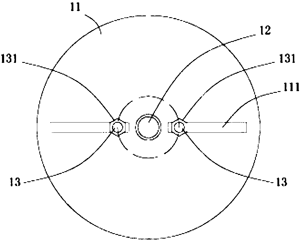
[0021] The present invention proposes a puller 1 which is convenient for maintenance and repair of the impeller, which is mainly used for disassembling the impeller 2 . For example, the impeller 2 of the disassembled centrifugal fan is pulled out from its shaft 3 . Wherein the central position of the impeller 2 is provided with a shaft hole, and the impeller 2 is provided with a plurality of loading and unloading holes 22 around the shaft hole, and the rotating shaft 3 that drives the impeller 2 to rotate is accommodated in the shaft hole. Such as figure 1 and figure 2 Shown, an embodiment of the puller 1 of the present invention. In Embodiment 1, the puller 1 includes a force receiving plate 11 , a lead screw 12 and a plurality of fixing bolts 13 .

[0022] Such as figure 1 and figure 2 As shown, in Embodiment 1, one end of the lead screw 12 passes through the force plate 11 to extend into the shaft hole of the impeller 2 and abut against the rotating shaft 3, and the ...

Embodiment approach 2

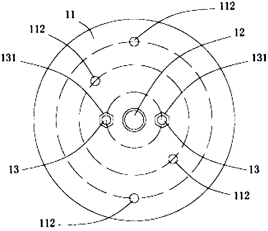
[0029] Another embodiment of the puller 1 of the present invention is substantially the same as Embodiment 1, the difference is: as image 3 As shown, in Embodiment 2, the adjustment groove 111 is replaced by a hole opened on the force receiving plate 11 . Specifically, a central hole with a screw thread is opened at the central position of the force plate 11 for passing the lead screw 12 and screwing it. In addition, a plurality of through holes 112 are opened in the circumferential position of the force receiving plate 11 for respectively passing through a plurality of fixing bolts 13 . It should be noted that, if image 3 As shown, the opening manner of the plurality of through holes 112 should correspond to the specific distribution positions of the loading and unloading holes 22 of the impeller 2 . Moreover, in order to make the puller 1 applicable to impellers 2 of various specifications, the distances between the through holes 112 opened on the force plate 11 and the ...


PUM


Abstract

The invention provides an impeller pulling device making an impeller to be overhauled and maintained simply and conveniently. The impeller pulling device is used for disassembling the impeller, the impeller comprises a rotating shaft and assembling and disassembling holes, the impeller pulling device comprises a stressed plate, a lead screw and a plurality of fixing bolts, the lead screw penetrates through the stressed plate to be used for extending into a shaft hole and abutting against the rotating shaft, the lead screw and the stressed plate are in threaded connection fit so as to guide thelead screw, in the case of the plurality of fixing bolts, each fixing bolt penetrates through the stressed plate to be used for being connected in the corresponding assembling and disassembling holein a threaded mode, and each fixing bolt is fixed on the stressed plate through a fastening piece. According to the provided impeller pulling device, the structure is simple, moreover, the use is convenient, the impeller pulling device can be used for rapidly and nondestructively disassembling the impeller of a centrifugal fan and the like, meanwhile, in the case of the provided impeller pulling device, due to the fact that the impeller can not deform in the process of disassembling the impeller through the impeller pulling device, the overhaul and maintenance time is shortened, and the perfectness rate of the impeller is guaranteed.

Description

technical field [0001] The invention relates to the technical field of impeller overhaul and maintenance, in particular to a puller with convenient impeller overhaul and maintenance Background technique [0002] As the core component of equipment such as centrifugal fans, the impeller needs to be pulled out from the shaft for replacement or maintenance on a regular basis. Existing impellers, such as those installed in centrifugal fans, such as figure 1 As shown, the central position of the impeller 2 is provided with a shaft hole 21, and a plurality of loading and unloading holes 22 are provided around the shaft hole 21 on the impeller 2, and the rotating shaft (not shown) driving the impeller 2 is accommodated in the shaft hole 21, and, The end of the rotating shaft 3 is exposed through the shaft hole 21 . [0003] At present, the process of pulling out the impeller from the rotating shaft is mainly completed by a puller. Existing pullers, such as claw-type pullers, are ...

Claims


Application Information

Patent Timeline
Patent Type & Authority Applications(China)
IPC IPC(8): B25B27/02F04D29/62
Inventor 安武坤
Owner 安武坤
Learn More