Cloth feeding mechanism and additional feeding mechanism of digital printing machine

A digital printing machine and additional technology, applied in printing, typewriter, thin material processing and other directions, can solve the problems of bonding and fixing product defects, affecting printing quality, inaccurate control of constant tension, etc., to achieve cost-effective and competitive Quite good, the effect of saving human, material and financial resources

Inactive Publication Date: 2019-06-04
广东希望高科数字技术有限公司
View PDF7 Cites 2 Cited by
  • Summary
  • Abstract
  • Description
  • Claims
  • Application Information

AI Technical Summary

Problems solved by technology

[0002] On existing digital printing machines, although the printing quality is closely related to the performance of the printing system, only high-quality printing equipment is not enough. The placement, movement and positioning of the fabric in production are directly related to the printing effect. Any wrinkles Errors in , deviation, adhesive fixation, etc. will lead to product defects, and even scrapped
However, the cloth loading mechanism of the existing digital printing machine is directly installed on the printing machine; it uses a speed-regulating motor to unwind, but the effective fabric will be stretched and deformed, which will affect the printing quality and reduce the pass rate of printing; there are also independent institutions on the market. The upper cloth frame adopts the principle of self-weight constant tension mechanism; this kind of upper cloth frame is not accurate enough to control the constant tension, and it will also affect the quality of the upper cloth

Method used


Image

  • Cloth feeding mechanism and additional feeding mechanism of digital printing machine
  • Cloth feeding mechanism and additional feeding mechanism of digital printing machine
  • Cloth feeding mechanism and additional feeding mechanism of digital printing machine

Examples


Embodiment Construction

[0018] The specific implementation manners of the present invention will be described in further detail below in conjunction with the accompanying drawings.

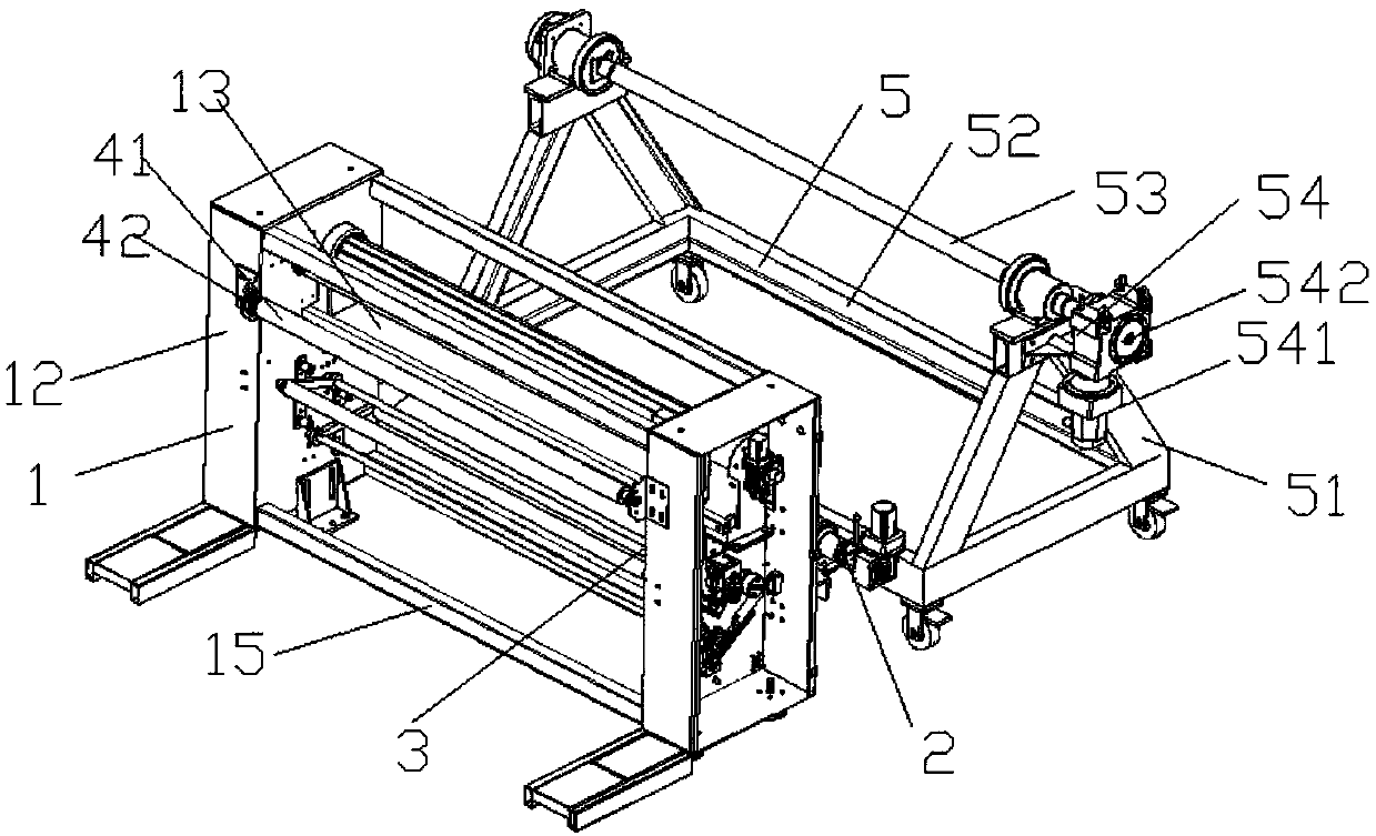
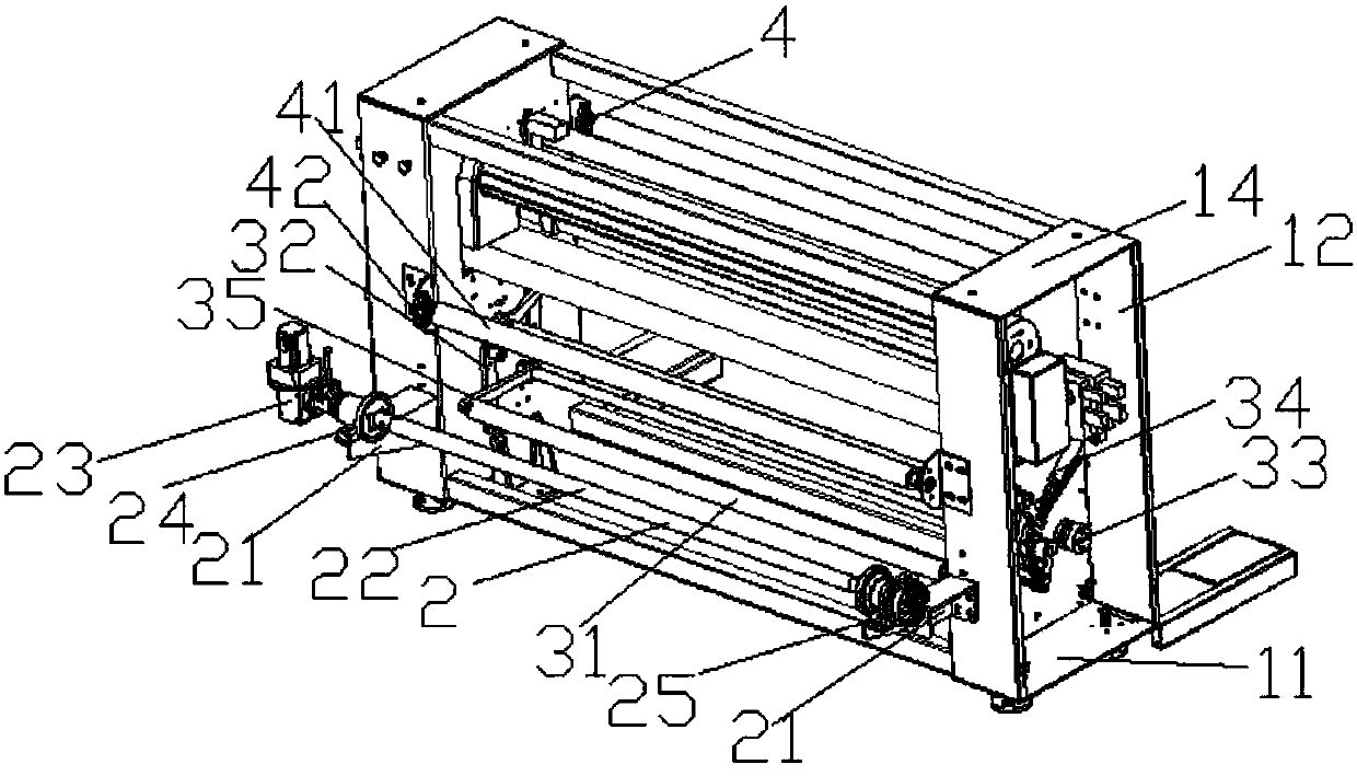
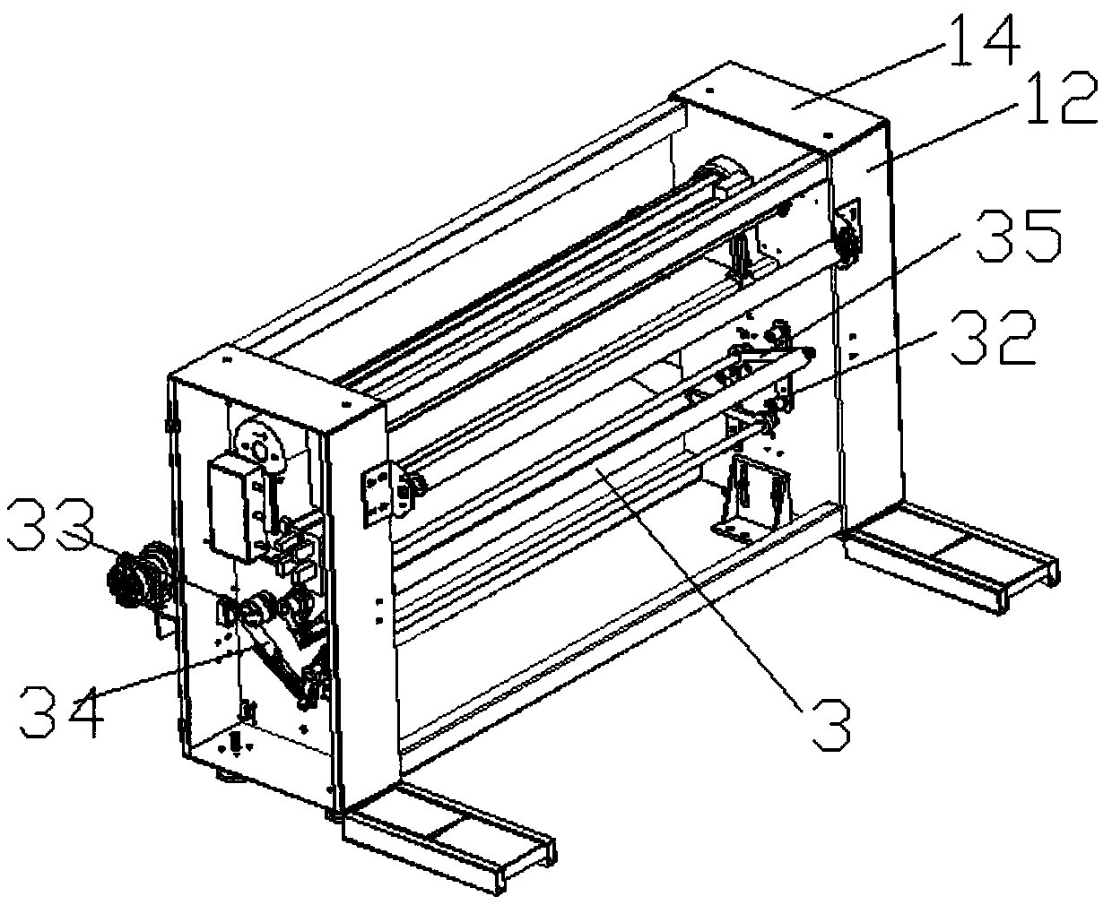
[0019] Referring to accompanying drawing, the present invention comprises the frame 1 that is made up of bottom plate 11, side plate 12, cover 13, horizontal plate 14, square pipe 15, and frame 1 is fixed by two groups of tops by horizontal plate 14, and bottom is fixed by bottom plate 11. The connected side plate 12 is composed of a square tube 15 and a cover 13 after two groups are arranged oppositely. It is characterized in that: the frame 1 is provided with a horizontally arranged feeding mechanism 2, a constant tension mechanism 3, and a guide roller. Agency 4;

[0020] The feeding mechanism 2 is composed of a feeding mechanism base 21, an air expansion roller 22, a motor mechanism 23, a clutch 24 and a braking mechanism 25;

[0021] Described constant tension mechanism 3 is made of constant tension rotating roller...


PUM


Abstract

The invention discloses a cloth feeding mechanism and an additional feeding mechanism of a digital printing machine. The purpose is to provide the cloth feeding mechanism and the additional feeding mechanism of the digital printing machine with high yield, less time and labor and good economy. The cloth feeding mechanism comprises a machine frame composed of a bottom plate, side plates, a cover, atransverse plate and a square tube, the machine frame is formed by combining two groups of oppositely-arranged side plates, the square tube and the cover, wherein the upper parts of the side plates are fixedly connected by the transverse plate and the lower parts of the side plates are fixedly connected by the bottom plate. The cloth feeding mechanism is characterized in that the machine frame isprovided with a feeding mechanism, a constant tension mechanism and a guiding roller mechanism which are arranged horizontally; and the cloth feeding mechanism and the additional feeding mechanism ofthe digital printing machine are mainly used for printcloth production.

Description

technical field [0001] The invention relates to the cloth printing industry, in particular to a cloth loading mechanism of a digital printing machine and an additional feeding mechanism thereof. Background technique [0002] On existing digital printing machines, although the printing quality is closely related to the performance of the printing system, only high-quality printing equipment is not enough. The placement, movement and positioning of the fabric during production are directly related to the printing effect. Any wrinkles Mistakes in , deviation, bonding, etc. will lead to product defects, and even scrapped in serious cases. However, the cloth feeding mechanism of the existing digital printing machine is directly installed on the printing machine; the speed-adjusting motor is used to unwind, but the effective fabric will be stretched and deformed, which will affect the printing quality and reduce the pass rate of printing; there are also independent institutions on...

Claims


Application Information

Patent Timeline
Patent Type & Authority Applications(China)
IPC IPC(8): B65H23/26B65H23/038B65H23/182B41J3/407
Inventor 何小燕
Owner 广东希望高科数字技术有限公司
Why Eureka
Try Eureka