
Edge cutting and edgings discharge device for embroidery machinery

A technology of exporting device and embroidery machine, applied in embroidery machine, embroidery machine mechanism, auxiliary device and other directions, can solve the problems of wasting time and labor cost, edge trimming equipment failure, winding and other problems, and achieves convenient connection, easy disassembly and assembly, Avoid the effect of position shift

Inactive Publication Date: 2019-06-04
诸暨市伽马机电制造有限公司
View PDF0 Cites 0 Cited by
  • Summary
  • Abstract
  • Description
  • Claims
  • Application Information

AI Technical Summary

Problems solved by technology

[0002] The face cloth has a uniform width, and the length of the cloth is different after weaving. It needs to be trimmed on both sides. The current trimming is generally rolled out, and a rotating blade is set on both sides to cut off the edge of the cloth. However, the cut edge The strips are randomly dropped to the ground and piled up. If there are too many side strips accumulated for a long time, it is easy to cause winding, resulting in the failure of the trimming equipment. At the same time, manual cleaning and collection are required, which wastes time and labor costs.

Method used


Image

  • Edge cutting and edgings discharge device for embroidery machinery
  • Edge cutting and edgings discharge device for embroidery machinery
  • Edge cutting and edgings discharge device for embroidery machinery

Examples


Embodiment Construction

[0017] In the following, the technical solutions of the present invention will be further described in detail through embodiments and in conjunction with the drawings.

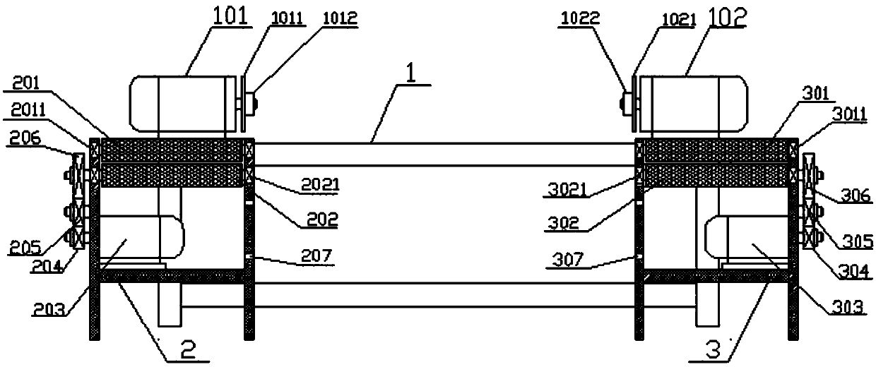
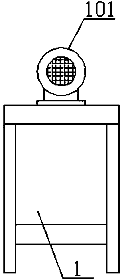
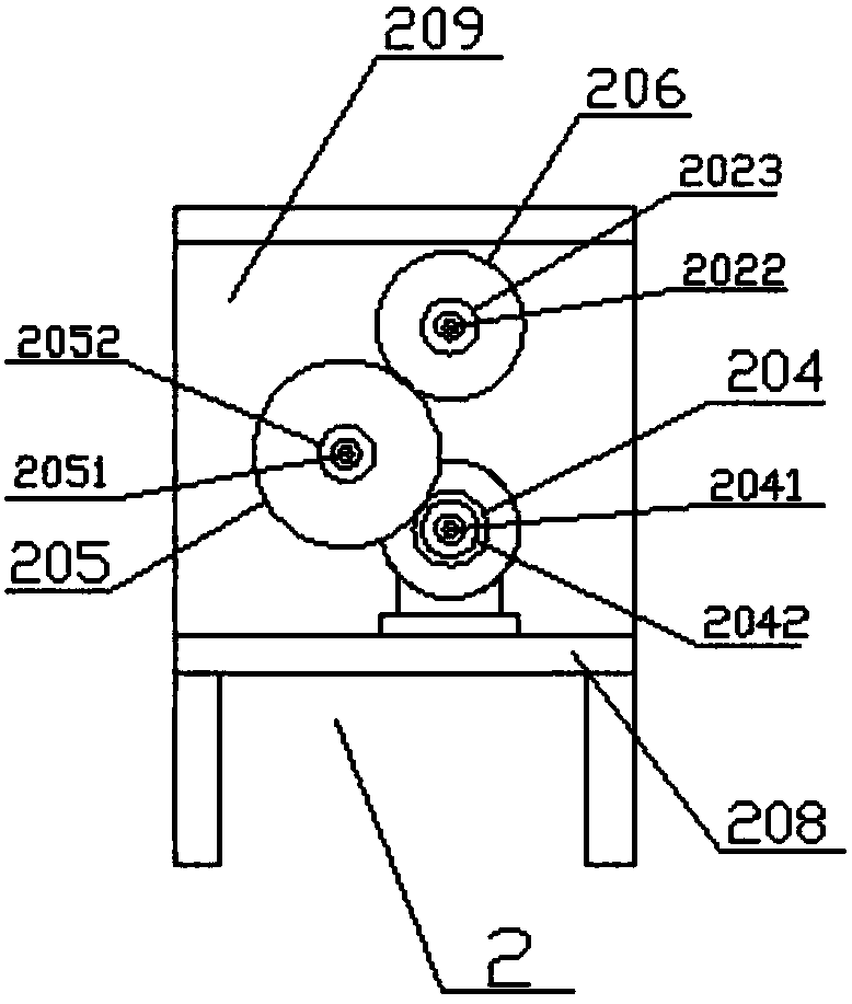
[0018] Such as Figure 1 ~ Figure 6 As shown, the edge trimming and edge strip leading-out device of the embroidery machine includes trimming frame 1, left leading-out device 2, right leading-out device 3, and both sides of the upper end of the trimming frame 1 are provided with a motor 101 and a motor 102 respectively. The first motor 101 shaft is provided with a cutter head 1011, and an external nut 1011 is used for locking, the motor second 102 shaft is provided with a cutter head two 1021, and the external nut two 1022 is used for locking. The left lead-out device 2 is provided with a number of fixing holes on the right side. One 207, a pressure roller 201 is set on the top, a roller 202 is set on the bottom, a platform 208 is set in the middle, and a side plate 209 is set on the left side. The two ends of th...


PUM


Abstract

The invention discloses an edge cutting and edgings discharge device for embroidery machinery, comprising an edge cutting frame, a left discharge device, and a right discharge device. motors I are arranged on two sides of the upper end of the edge cutting frame respectively; each motor shaft is provided with a cutter disc locked via a nut outside; the right side of each discharge device is provided with a plurality of fixing holes, a presser wheel is arranged above the discharge device, a roller is arranged below the discharge device, a platform is in the middle, a side plate is arranged on the left, two ends of the presser wheel are provided with bearings connected with the left discharge device, two ends of the roller are provided with bearings connected with the left discharge device, the left end of the roller is provided with a roller shaft that is provided with a gear, a flat washer is arranged outside the gear and is fixed via a screw, each side plate is provided with an arc slot which is provided with a moving shaft, the moving shaft is provided with a gear, and a flat washer is arranged outside the gear and fixed via a screw; one motor is arranged on each platform, the motor shaft of each motor is provided with a gear, and a flat washer is arranged outside the gear and fixed via a screw. After a shell fabric is fed and cut according to a set width, edges are automatically discharged and recycled; tangling is avoided, and manpower cost is reduced.

Description

Technical field [0001] The invention relates to a trimming and leading-out device of face cloth, in particular to a trimming and edge leading-out device of an embroidery machine. Background technique [0002] The face cloth has a uniform width, and the length of the cloth after weaving is different. It needs to be trimmed on both sides. The current trimming is generally rolled out. There are rotating blades on both sides to cut the side of the cloth. However, the cut side The strips randomly fall to the ground and accumulate. If too many strips are accumulated for a long time, it is easy to cause entanglement, leading to failure of the trimming equipment. At the same time, manual cleaning and collection are required, which wastes time and labor costs. Summary of the invention [0003] The purpose of the present invention is to overcome the above-mentioned shortcomings of the prior art, and provide an embroidery machine trimming and trimming device, including a trimming frame, a le...

Claims


Application Information

Patent Timeline
IPC IPC(8): D05C13/00D06H7/04
Inventor 郦潮辉
Owner 诸暨市伽马机电制造有限公司
Learn More