Reinforced concrete prefabricated overall-poured house structure and construction method thereof

A technology of reinforced concrete and houses, which is applied in the direction of building structure and construction, can solve the problems of poor connection stability between floor and wall panels, and achieve the goals of improving convenience and precision, improving the stability of fixed connections, and improving assembly efficiency Effect

Active Publication Date: 2019-06-04
WENZHOU DONGLIAN MUNICIPAL ENG CO LTD
View PDF6 Cites 10 Cited by
  • Summary
  • Abstract
  • Description
  • Claims
  • Application Information

AI Technical Summary

Problems solved by technology

[0004] However, the above-mentioned fixing method between the floor slab and the wall slab is only completed by pouring concrete, which makes the connection between the floor slab and the wall slab less stable.

Method used


Image

  • Reinforced concrete prefabricated overall-poured house structure and construction method thereof
  • Reinforced concrete prefabricated overall-poured house structure and construction method thereof
  • Reinforced concrete prefabricated overall-poured house structure and construction method thereof

Examples


Embodiment 1

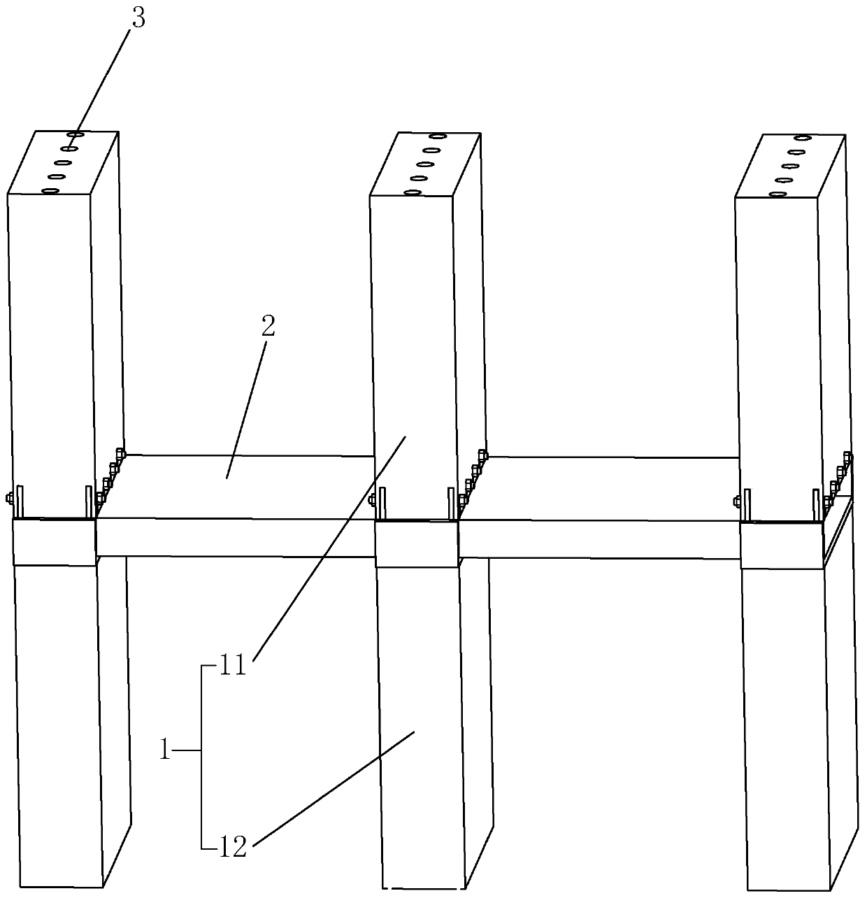
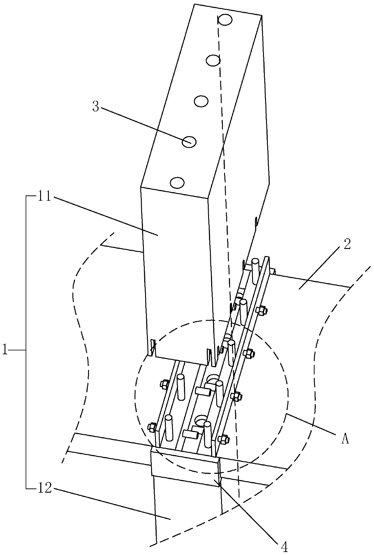
[0040] A reinforced concrete prefabricated integral pouring house structure and its construction method, such as figure 1 and image 3 As shown, it includes a wall panel 1 and a floor slab 2. The wall panel 1 includes an upper wall 11 and a lower wall 12. The lower wall 12 is directly fixed to the ground and perpendicular to the ground during prefabrication. The lower wall 12 includes spaced apart Multiple floor slabs 2 are also provided with multiple floor slabs 2, and the tops of every two adjacent lower walls 12 are erected with a floor slab 2. In the gap, the upper wall 11 is located directly above the lower wall 12 and the upper wall 11 and the lower wall 12 are parallel to each other, and the upper wall 11 and the lower wall 12 are provided with a plurality of pouring holes 3 vertically penetrating themselves. The bottom of the upper wall 11 abuts against the end positions of two adjacent floor slabs 2. The upper surface of the floor slabs 2 is fixedly provided with a p...

Embodiment 2

[0047] A construction method for a reinforced concrete prefabricated cast-in-place house structure, the specific method of which is as follows:

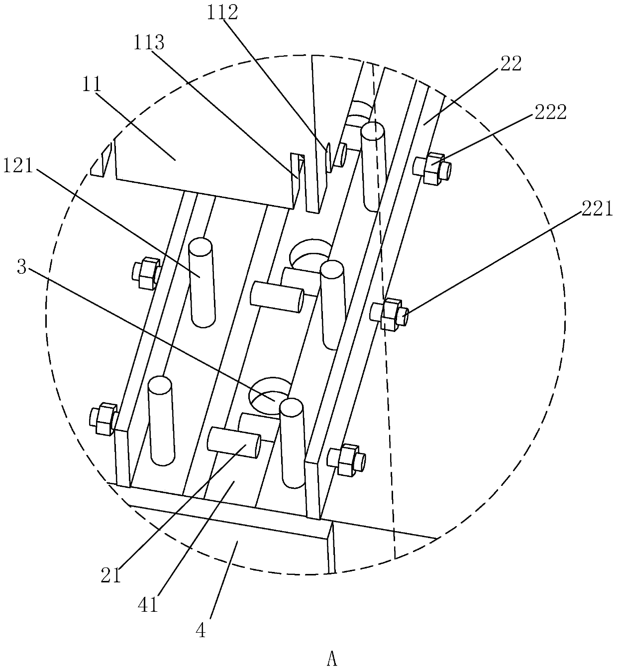
[0048] S1: The floor 2 and wall 1 are prefabricated. The steel bars at both ends of the floor 2 pass through the floor 2 horizontally to form connecting steel bars 21. The steel bars at both ends of the floor 2 pass through the floor 2 vertically to form fixed steel bars 121. During prefabrication, direct pouring is fixed connection with the ground;

[0049] S2: Put the floor 2 in the installation groove 41 at the top of the lower wall 12, so that there is a gap between the two adjacent floors 2 at the top of the same lower wall 12 close to each other, and then place the adjacent floors 2 The connecting steel bars 21 are welded together;

[0050] S3: Move the prefabricated upper wall 11 to the top of the floor 2 through hoisting, and the upper wall 11 is located directly above the lower wall 12, so that the fixed steel bar 121 is fa...


PUM


Abstract

The invention relates to a reinforced concrete prefabricated overall-poured house structure and a construction method thereof, and belongs to the technical field of house structure systems. Accordingto the key points of the technical scheme, the reinforced concrete prefabricated overall-poured house structure comprises prefabricated floors and wall plates, each wall plate comprises an upper walland a lower wall, the bottoms of the lower walls are fixedly connected with the ground, one floor is erected at the top ends of every two corresponding adjacent lower walls, gaps used for pouring concrete are reserved between the ends, close to each other, of the adjacent floors, the upper walls are located over the lower walls, the bottom ends of the upper walls abut against the top ends, close to each other, of the two adjacent floors, the wall plates are provided with vertically penetrating pouring holes, fixing holes are formed in the positions, on the two sides of the pouring holes, of the upper walls, fixing steel bars matched with the fixing holes are fixedly formed in the upper surfaces of the floors, and the top ends of the fixing holes communicate with the pouring holes. The effect of improving the fixing stability between the floors and the wall plates is achieved.

Description

technical field [0001] The invention relates to the technical field of house structure systems, in particular to a reinforced concrete prefabricated whole cast house structure and a construction method thereof. Background technique [0002] The building structure is generally a structural system composed of columns, beams, and slabs. Beams, slabs, and columns can be constructed in two ways: prefabricated and cast-in-place or cast-in-place. The large-scale increase, the extensive problems of its bulkiness, large consumption of materials, large consumption of wooden formwork, and large amount of labor are becoming more and more prominent. Therefore, prefabricated and poured construction methods are now mostly used. [0003] The existing reinforced concrete prefabricated whole house structure generally includes wall panels and floor slabs erected on the wall panels. After the erection is completed, concrete is poured at the erection positions of the floor slabs and wall panels,...

Claims


Application Information

Patent Timeline
Patent Type & Authority Applications(China)
IPC IPC(8): E04B1/38E04B1/41
Inventor 朱余任建华
Owner WENZHOU DONGLIAN MUNICIPAL ENG CO LTD
Why Eureka
Try Eureka