Proton exchange membrane fuel cell bipolar plate three-dimensional flow field

A proton exchange membrane, fuel cell technology, applied in fuel cells, electrochemical generators, circuits, etc., can solve the problems affecting cell performance, large resistance of diffusion layer, large gas pressure drop, etc. , The effect of simplifying the battery system and improving the stability

Active Publication Date: 2019-06-04
QINGDAO INST OF BIOENERGY & BIOPROCESS TECH CHINESE ACADEMY OF SCI
View PDF5 Cites 5 Cited by
  • Summary
  • Abstract
  • Description
  • Claims
  • Application Information

AI Technical Summary

Problems solved by technology

However, due to the discontinuous flow channel, the resistance of the diffusion layer is relatively large, and the gas pressure drop is relatively large, which will easily damage the catalytic layer and affect the performance of the battery (Document 1: Yi Baolian, Fuel Cell-Principle, Technology and Application, Chemical Industry Press , 2003)

Method used


Image

  • Proton exchange membrane fuel cell bipolar plate three-dimensional flow field
  • Proton exchange membrane fuel cell bipolar plate three-dimensional flow field
  • Proton exchange membrane fuel cell bipolar plate three-dimensional flow field

Examples


Embodiment 1

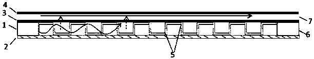
[0027] Such as figure 1 and 2 The schematic diagram of the three-dimensional flow field of the fuel cell bipolar plate with the function of baffle and water separation is shown, in which the three-dimensional flow field structure is formed by perforating and bending on a CNC punching machine to form the bending process of the perforated plate, specifically:

[0028] The three-dimensional flow field is located between the membrane electrode and the separator to form a sealed structure. The end surface of the flow channel is one or more tooth-shaped, and fluid holes are opened between the tooth root and the tooth top on both sides of each tooth.

[0029] The tooth-shaped end face is square. The teeth in the flow field are alternately arranged with convex and concave structures, forming the ridges and flow channels of the three-dimensional flow field.

[0030] The distance between the dedendum and the dedendum is 0.4mm, and the distance between any two adjacent dedendums or ded...

Embodiment 2

[0034] Such as image 3 and 4 A schematic diagram of the structure of the fluid holes in different directions of the three-dimensional flow field is shown, in which the three-dimensional flow field structure adopts the punching process of the perforated plate, specifically:

[0035] The three-dimensional flow field is located between the membrane electrode and the separator to form a sealed structure. The end surface of the flow channel is one or more tooth-shaped, and fluid holes are opened between the tooth root and the tooth top on both sides of each tooth.

[0036] The tooth-shaped end surface is an isosceles trapezoid. The teeth in the flow field are alternately arranged with convex and concave structures, forming the ridges and flow channels of the three-dimensional flow field.

[0037] The distance between the dedendum and the dedendum is 0.5mm, and the distance between any two adjacent dedendums or dedendums is 0.8mm (vertical distance); the diameter of the fluid hol...


PUM


Abstract

The invention relates to the application field of the proton exchange membrane fuel cell technology and particularly relates to a three-dimensional flow field with high-efficiency drainage of a protonexchange membrane fuel cell. The three-dimensional flow field forms a sealing structure between a membrane electrode and a separator, wherein a passage end surface is in the shape of one or more teeth, and fluid holes are formed on two sides of each tooth. The three-dimensional flow field of the invention realizes the purpose of effective water management without using external equipment such asa hydrogen circulation pump, therefore, the pulse discharge amount is greatly reduced, and the gas utilization rate can be effectively improved compared with a conventional two-dimensional flow field.The invention is applicable to a cathode-anode flow field of the proton exchange membrane fuel cell, is especially suitable for an anode side flow field, and has very important meanings for simplifying a battery system and improving the gas utilization rate.

Description

technical field [0001] The invention relates to the application field of proton exchange membrane fuel cell technology, in particular to a three-dimensional flow field for efficient drainage of proton exchange membrane fuel cell. Background technique [0002] A fuel cell is a power generating device that converts chemical energy in fuel and oxidant directly into electrical energy. Among the many types of fuel cells that have been developed, the proton exchange membrane fuel cell is a device that is highly efficient, environmentally friendly, and has no combustion reaction. It uses hydrogen or hydrogen-rich gas as fuel and air or oxygen as oxidant, so it is considered the most efficient. The preferred energy source for application prospects. [0003] PEMFC mainly constitutes the core components. In addition to the membrane electrode, the bipolar plate is also an important core component of the PEMFC. It is the main part of the volume and weight of the PEMFC battery. It has a...

Claims


Application Information

Patent Timeline
Patent Type & Authority Applications(China)
IPC IPC(8): H01M8/0258H01M8/0263
CPCY02E60/50
Inventor 李晓锦白兆圆苗纪远林春明
Owner QINGDAO INST OF BIOENERGY & BIOPROCESS TECH CHINESE ACADEMY OF SCI
Why Eureka
Try Eureka