Electric cylinder used for magnetic transmission

A technology of magnetic transmission and electric cylinder, which is applied in the direction of electric components, transmission devices, permanent magnet clutches/brakes, etc., can solve problems such as screw instability, avoid instability, improve service life and protection level, and improve stability Effect

Active Publication Date: 2019-06-04
上海弘赫自动化技术有限公司
View PDF4 Cites 0 Cited by
  • Summary
  • Abstract
  • Description
  • Claims
  • Application Information

AI Technical Summary

Problems solved by technology

[0003] The technical task of the present invention is to address the above deficiencies and provide an el

Method used


Image

  • Electric cylinder used for magnetic transmission
  • Electric cylinder used for magnetic transmission

Examples


Embodiment 1

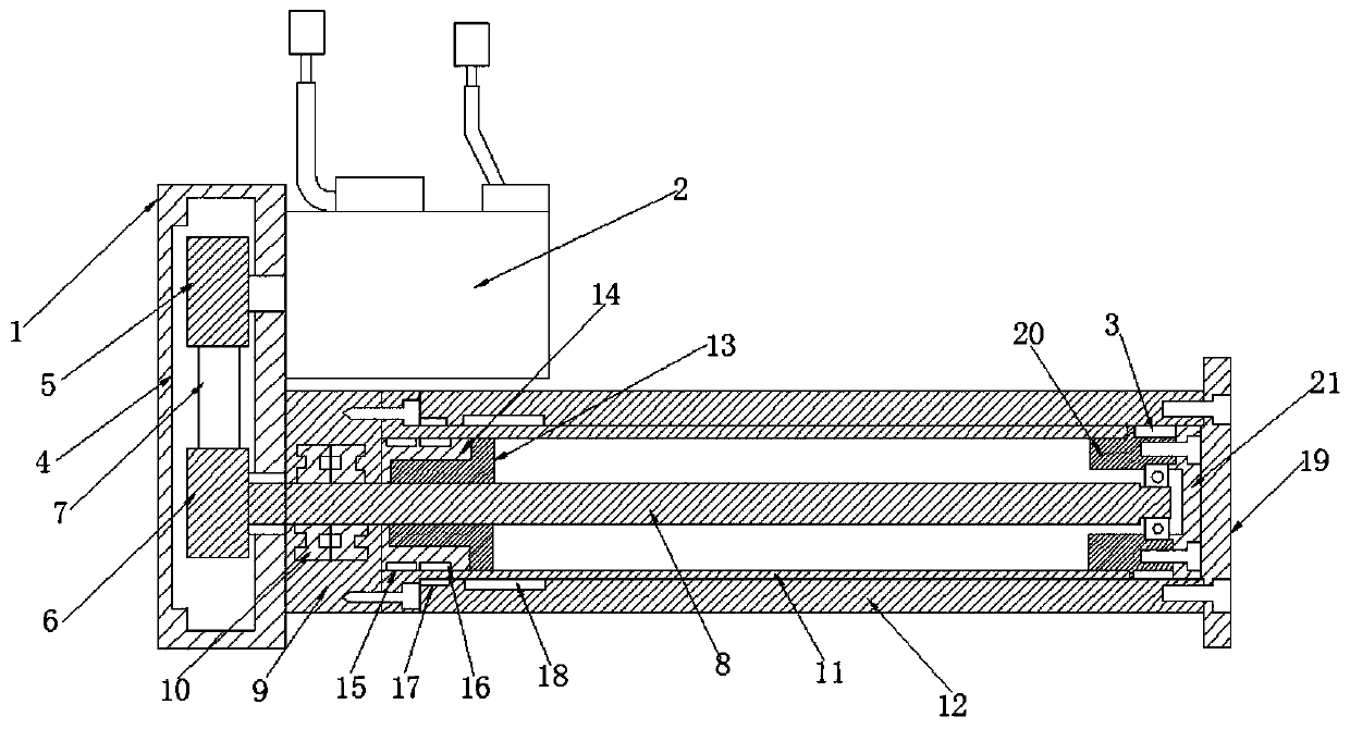
[0018] Embodiment one, such as figure 1 As shown, an electric cylinder for magnetic transmission according to an embodiment of the present invention includes a base 1, a motor 2 is provided on one side of the base 1, and a cavity 4 is provided on the inner side of the base 1. The output shaft of the motor 2 is provided with a belt pulley 5 at the inner upper end of the cavity 4, and the inner lower end of the cavity 4 is provided with a belt pulley 2 6, between the belt pulley 5 and the belt pulley 2 6 A synchronous belt 7 is provided between them, a ball screw 8 is interspersed in the pulley 2, a bearing seat 9 is provided at the lower end of one side of the base 1, and a cylinder body 11 is provided at one side of the bearing seat 9, The outer side of the cylinder 11 is covered with a piston rod 12 , the ball screw 8 and inside the cylinder 11 are covered with a ball nut 13 , and the outer side of the ball nut 13 is covered with a nut sleeve 14 , the nut sleeve 14 is equipp...

Embodiment 2

[0019] Embodiment two, such as figure 1 As shown, the motor 2 is connected in parallel with the cylinder body 11 and the piston rod 12 in parallel.

Embodiment 3

[0020] Embodiment three, such as figure 1 As shown, the strong magnetic steel one 16 and the strong magnetic steel two 17 are permanent magnetic steels, and the magnetism between the two is opposite, so that the strong magnetic steel one 16 drives the strong magnetic steel two 17 sports.


PUM


Abstract

The invention discloses an electric cylinder used for magnetic transmission, which comprises a base, wherein the upper end of one side of the base is provided with a motor, the inner side of the baseis provided with a cavity, a belt wheel 1 is arranged on an output shaft of the motor and positioned at the upper end inside the cavity, the lower end inside the cavity is provided with a belt wheel 2, a synchronous belt is arranged between the belt wheel 1 and the belt wheel 2, a ball screw is inserted in the belt wheel 2, the lower end of the one side of the base is provided with a bearing pedestal, one side of the bearing pedestal is provided with a cylinder body, a piston rod sleeves the cylinder body, a ball nut sleeves the ball screw and is arranged inside the cylinder body, a nut sleevesleeves the ball nut, the nut sleeve is matched with a circle of guiding belt, the nut sleeve is further provided with magnetic steel 1 with strong magnetism, one side of the piston rod is provided with magnetic steel 2 with strong magnetism which is matched with the magnetic steel 1 with strong magnetism, one end of the piston rod is provided with a piston rod output flange, one end, close to the piston rod output flange, of the cylinder body is provided with a front-end bearing pedestal, and one end of the ball screw penetrates the center of the front-end bearing pedestal.

Description

technical field [0001] The invention relates to the field of electric cylinders, in particular to an electric cylinder for magnetic transmission. Background technique [0002] At present, the electric cylinder is a kind of linear actuator in industrial automation equipment. It transmits the power of the servo motor to the screw through the transmission mechanism, and then converts the rotary motion of the screw into the linear motion of the nut through the screw and nut mechanism. , and then transmitted to the piston rod, so as to realize the telescopic movement of the piston rod relative to the cylinder. Compared with common hydraulic cylinders, pneumatic cylinders, etc., the electric cylinder responds quickly and has high execution accuracy. However, the screw rod of the traditional electric cylinder belongs to a single support structure, and the stability of the pressure rod is poor. The movable end screw rod is easily shaken by centrifugal force Friction with the piston...

Claims


Application Information

Patent Timeline
IPC IPC(8): H02K7/06H02K49/10F16H25/22
Inventor 姜建唐姗姗孙作成
Owner 上海弘赫自动化技术有限公司
Why Eureka
Try Eureka