
A pulse load power supply system and its control method

A technology of power supply system and pulse load, which is applied in the direction of control/regulation system, electrical components, and adjustment of electrical variables, etc. It can solve the problems of low power density of the system, increase the filter parameters of the input terminal, affect the electrical equipment, etc., and achieve power conversion The number of stages is small, the effect of realizing voltage compensation and reducing the volume of the capacitor

Active Publication Date: 2021-01-19
NANJING UNIV OF AERONAUTICS & ASTRONAUTICS
View PDF2 Cites 0 Cited by
  • Summary
  • Abstract
  • Description
  • Claims
  • Application Information

AI Technical Summary

Problems solved by technology

[0003] 1. The power supply is designed according to the peak power of the pulse load, the volume and weight are large, and the system power density is low;
[0004] 2. Lack of control over input current
The current pulse generated by the pulse load will be conducted to the input end of the power system through the converter, affecting other electrical equipment
At the same time, in order to suppress the pulsating current at the input end, it is necessary to increase the filter parameters at the input end, resulting in a decrease in the overall efficiency of the system;
[0005] 3. Lack of precise control of the output voltage
However, there are still two problems unsolved in this solution: 1. The bidirectional converter still needs to be designed according to the peak pulse power; stage conversion, the system efficiency is not high

Method used


Image

  • A pulse load power supply system and its control method
  • A pulse load power supply system and its control method
  • A pulse load power supply system and its control method

Examples


Embodiment approach 1

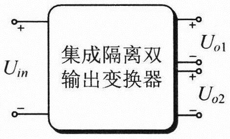
[0036] Embodiment 1: An integrated isolated dual-output converter is used to provide input ports and two output ports at the same time. The schematic diagram of its structure is shown in the attached figure 2 shown. In actual implementation, there are many types of circuit topologies to choose from for isolated dual-output converters, such as the literature "Y.Chen, Y.Kang, S.Nie and X.Pei, The Multiple-Output DC-DCConverter With Shared ZCS Lagging Leg , in IEEE Transactions on PowerElectronics, vol.26, no.8, pp.2278-2294, Aug.2011." The dual-output converter topology mentioned in "A Multioutput LLC Resonant Converter With Semi-Active Rectifiers , inIEEE Journal of Emerging and Selected Topics in Power Electronics, vol.5, no.4, pp.1819-1827, Dec.2017." The dual output converter topology mentioned in.

Embodiment approach 2

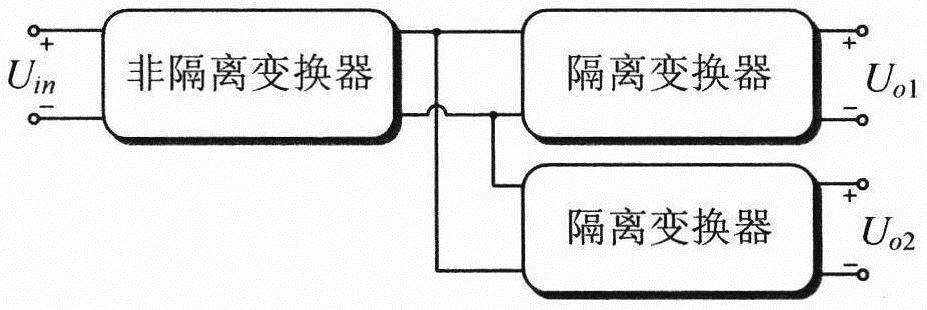
[0037] Embodiment 2: A combination of a non-isolated converter and two isolated converters is used to provide one input port and two output ports, wherein the input port of the non-isolated converter serves as the input port of the isolated dual-output conversion module, and the non-isolated converter's The output ports are connected to the input ports of the two isolation converters, and the output ports of the two isolation converters are used as the two output ports of the isolated dual-output conversion module; the structural diagram of the second embodiment is shown in the attached image 3 shown. In specific implementation, any non-isolated DC converter and isolated DC converter can be used to construct an isolated dual-output conversion module. For example, Buck converter is selected for non-isolated converter, and LLC resonant converter is selected for isolated converter.

Embodiment approach 3

[0038] Embodiment 3: Two isolated converters are combined to provide one input port and two output ports, wherein the input port of one isolated converter is used as the input port of the isolated dual-output conversion module, and the output port of the isolated converter is connected to another The input port of one isolation converter serves as the second output port of the isolated dual-output conversion module, and the output port of the other isolation converter serves as the first output port of the isolated dual-output conversion module. The structural schematic diagram of the third embodiment is attached Figure 4 shown. In a specific implementation, any isolated DC converter can be used to construct an isolated dual-output conversion module, and the circuit topologies of the two isolated DC converters can be the same or different. For example, both isolation converters use LLC resonant converters.

[0039] In the pulse load power supply system of the present invent...


PUM


Abstract

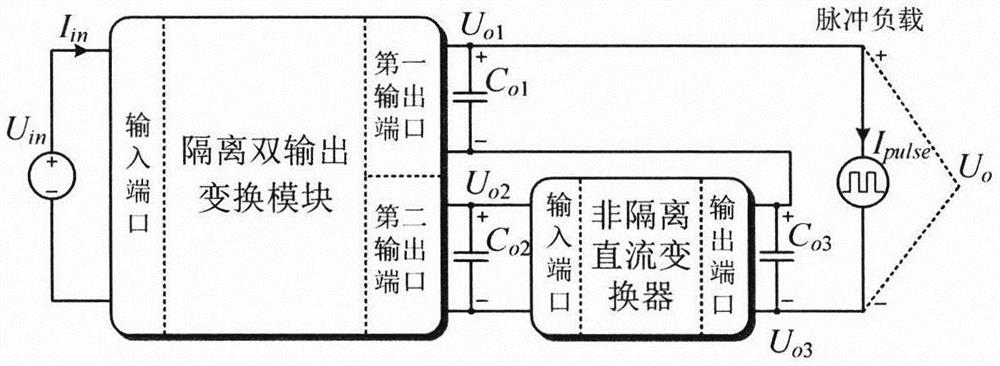
The invention discloses a pulse load power system and a control method thereof. The pulse load power system is composed of an isolated dual-output transformation module and a non-isolated DC converter, the isolated dual-output transformation module comprises an input port and two output ports, the second output port of the isolated dual-output transformation module is connected with the input portof the non-isolated DC converter, the output port of the non-isolated DC converter and the first output port of the isolated dual-output transformation module are connected in series and serve as themaster system output port, and the master output port is connected with a pulse load. The isolated dual-output transformation module controls the voltage and input current of the first output port, and the non-isolated DC converter controls the total output voltage of the system. The system can inhibit current impact generated in the input port by pulse power effectively, the system power transmission level, the system efficiency and power density are reduced, and the system and method are especially suitable for application occasions with pulse load.

Description

technical field [0001] The invention relates to a power supply system, in particular to a pulse load power supply system and a control method thereof, and belongs to the field of power electronic conversion and power supply systems. Background technique [0002] Pulse loads are widely used in material surface treatment, biomedicine, food disinfection and other fields. It requires the power system to be able to provide stable voltage and pulse changing current. Traditional pulse load power supply systems have many disadvantages: [0003] 1. The power supply is designed according to the peak power of the pulse load, the volume and weight are large, and the system power density is low; [0004] 2. Lack of control over the input current. The current pulse generated by the pulse load will be conducted to the input end of the power system through the converter, affecting other electrical equipment. At the same time, in order to suppress the pulsating current at the input end, ...

Claims


Application Information

Patent Timeline
Patent Type & Authority Patents(China)
IPC IPC(8): H02M3/158H02M3/335
Inventor 高桪吴红飞高尚邢岩
Owner NANJING UNIV OF AERONAUTICS & ASTRONAUTICS
Learn More