A photovoltaic grid-connected inverter and its control method

A technology of inverters and photovoltaics, applied in photovoltaic power generation, AC network circuits, single-network parallel feeding arrangements, etc., can solve the problems of large DC bus capacitor voltage fluctuations, limited DC bus capacitors, and booster circuits not working, etc. Achieve the effects of increasing power density, reducing filter inductance value, and reducing output voltage variation amplitude

Active Publication Date: 2018-04-03
HOHAI UNIV
View PDF5 Cites 0 Cited by
  • Summary
  • Abstract
  • Description
  • Claims
  • Application Information

AI Technical Summary

Problems solved by technology

However, when the instantaneous absolute value of the AC grid voltage is lower than the output DC voltage of the photovoltaic module string, the electric energy output by the photovoltaic module still needs to be converted by a booster circuit, so the literature "K.Orgura, T.Nishida, E.Hiraki, M.Nakaoka , and S.Nagai.Time-sharing boost chooper cascaded dual mode single-phase sinewave inverter for solar photovoltaic power generation system.IEEEPESC 2004,pp.4763-4767" proposed that when the output voltage of the photovoltaic module string is lower than the absolute value of the instantaneous value of the grid voltage value, so that the DC bus capacitor voltage between the boost converter and the inverter is equal to the absolute value of the instantaneous value of the grid voltage; and when the output voltage of the photovoltaic module string is higher than the absolute value of the instantaneous value of the grid voltage, the boost circuit Not working
However, this control method limits the capacity of the DC bus capacitor, so the voltage ripple of the DC bus capacitor is relatively large, and the control is more complicated and difficult to implement.

Method used


Image

  • A photovoltaic grid-connected inverter and its control method
  • A photovoltaic grid-connected inverter and its control method
  • A photovoltaic grid-connected inverter and its control method

Examples


Embodiment 1

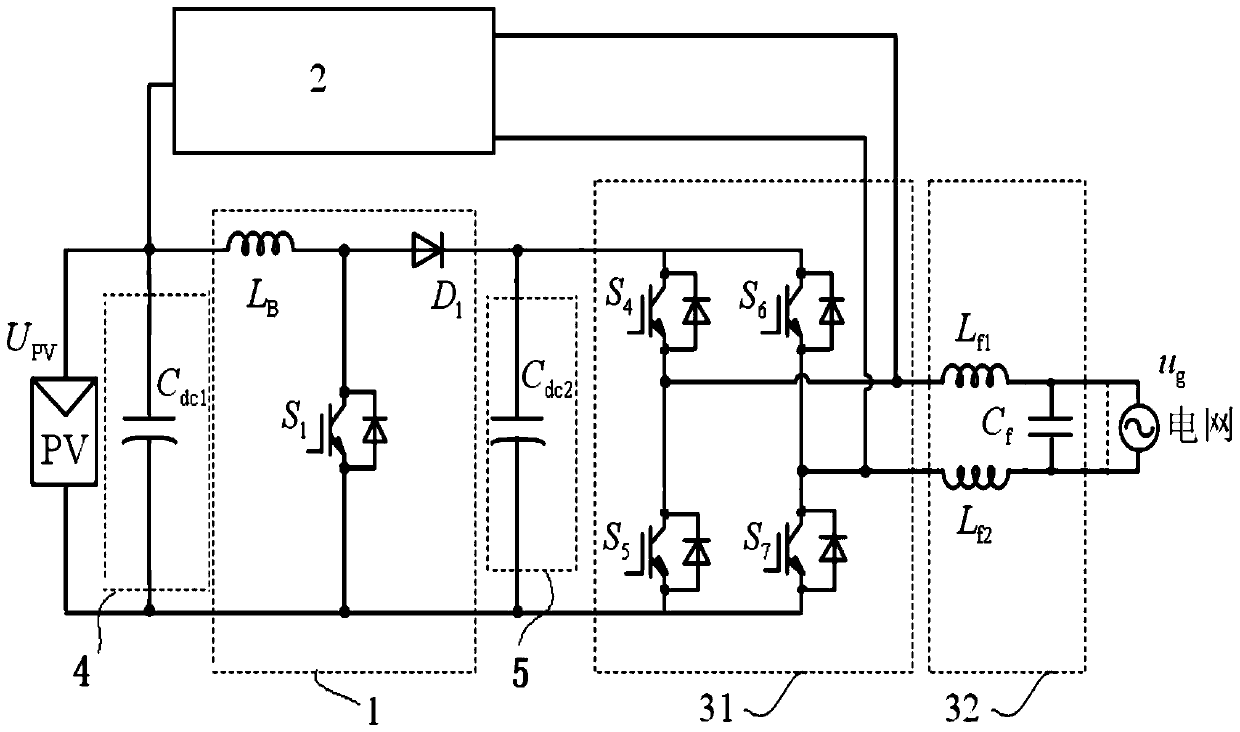
[0038] The photovoltaic grid-connected inverter described in Embodiment 1 adopts the DC bypass branch 2 of the first structure, which includes six working modes:

[0039] Mode 1: the fourth power switch tube S in the full-bridge inverter circuit 31 4 and the seventh power switch S 7 turn on, the other switches in the full-bridge inverter circuit 31 are turned off, and the grid current flows through the fourth power switch S in sequence 4 , the first filter inductance L f1 , grid u g , the second filter inductance L f2 , the seventh power switch tube S 7 ; The bridge arm voltage output by the full-bridge inverter circuit 31 is the second DC bus capacitor C dc2 Voltage;

[0040] Mode 2: the second power switch S in the DC bypass branch 2 2 turn on, the third power switch S 3 turn off, the seventh power switch tube S in the full-bridge inverter circuit 31 7 turn on, the other switch tubes in the full-bridge inverter circuit 31 are turned off, and the incoming current flo...

Embodiment 2

[0061] The photovoltaic grid-connected inverter described in Embodiment 2 adopts the DC bypass branch 2 of the first structure, which includes six working modes:

[0062] Mode 1: the fourth power switch tube S in the full-bridge inverter circuit 31 4 and the seventh power switch S 7 turn on, the other switches in the full-bridge inverter circuit 31 are turned off, and the grid current flows through the fourth power switch S in sequence 4 , the first filter inductance L f1 , grid u g , the second filter inductance L f2 , the seventh power switch tube S 7 ; The bridge arm voltage output by the full-bridge inverter circuit 31 is the second DC bus capacitor C dc2 Voltage;

[0063] Mode 2: the second power switch S in the DC bypass branch 2 2 turn on, the third power switch S 3 turn off, the fourth power switch tube S in the full-bridge inverter circuit 31 4 turn on, the other switches in the full-bridge inverter circuit 31 are turned off, and the grid current flows throug...


PUM


Abstract

The invention discloses a photovoltaic grid-connected inverter which comprises a first direct current bus capacitor branch, a second direct current bus capacitor branch, a boost converting circuit, a direct current bypass branch, a full-bridge inverter circuit and an alternating current filtering circuit, wherein the first direct current bus capacitor branch, the boost converting circuit, the second direct current bus capacitor branch, the full-bridge inverter circuit and the alternating current filtering circuit are sequentially connected in series; the input end of the first direct current bus capacitor branch is externally connected with a photovoltaic modules string; the output end of the alternating current filtering circuit is externally connected with a power grid; the direct current bypass branch is connected in parallel between the input end of the first direct current bus capacitor branch and the output end of the full-bridge inverter circuit. Meanwhile, the invention also discloses a control method for the photovoltaic grid-connected inverter. According to the photovoltaic grid-connected inverter and the control method thereof disclosed by the invention, the direct current bypass branch is introduced, so the problems in the prior art are solved.

Description

technical field [0001] The invention relates to a photovoltaic grid-connected inverter and a control method thereof, belonging to the technical field of power electronic converters. Background technique [0002] Due to the renewable and clean nature of solar energy, photovoltaic grid-connected power generation technology has developed rapidly. The output DC voltage of the photovoltaic module string is usually lower than the peak value of the AC grid voltage, so it needs to go through a first-stage boost circuit and then connect to the inverter to realize grid-connected operation, such as figure 1 shown. However, when the instantaneous absolute value of the AC grid voltage is lower than the output DC voltage of the photovoltaic module string, the electric energy output by the photovoltaic module still needs to be converted by a booster circuit, so the literature "K.Orgura, T.Nishida, E.Hiraki, M.Nakaoka , and S.Nagai.Time-sharing boost chooper cascaded dual mode single-phas...

Claims


Application Information

Patent Timeline
Patent Type & Authority Patents(China)
IPC IPC(8): H02M7/5387H02J3/38
CPCH02J3/383H02M1/32Y02E10/56
Inventor 张犁赵晋泉
Owner HOHAI UNIV
Why Eureka
Try Eureka