Oil-free screw compressor
A screw compressor, screw technology, applied in the direction of rotary piston machinery, mechanical equipment, machine/engine, etc., can solve the problem of difficult to completely prevent the infiltration of lubricating oil, and achieve the effect of preventing oil accumulation
- Summary
- Abstract
- Description
- Claims
- Application Information
AI Technical Summary
Problems solved by technology
Method used
Image

Examples
no. 1 Embodiment approach )
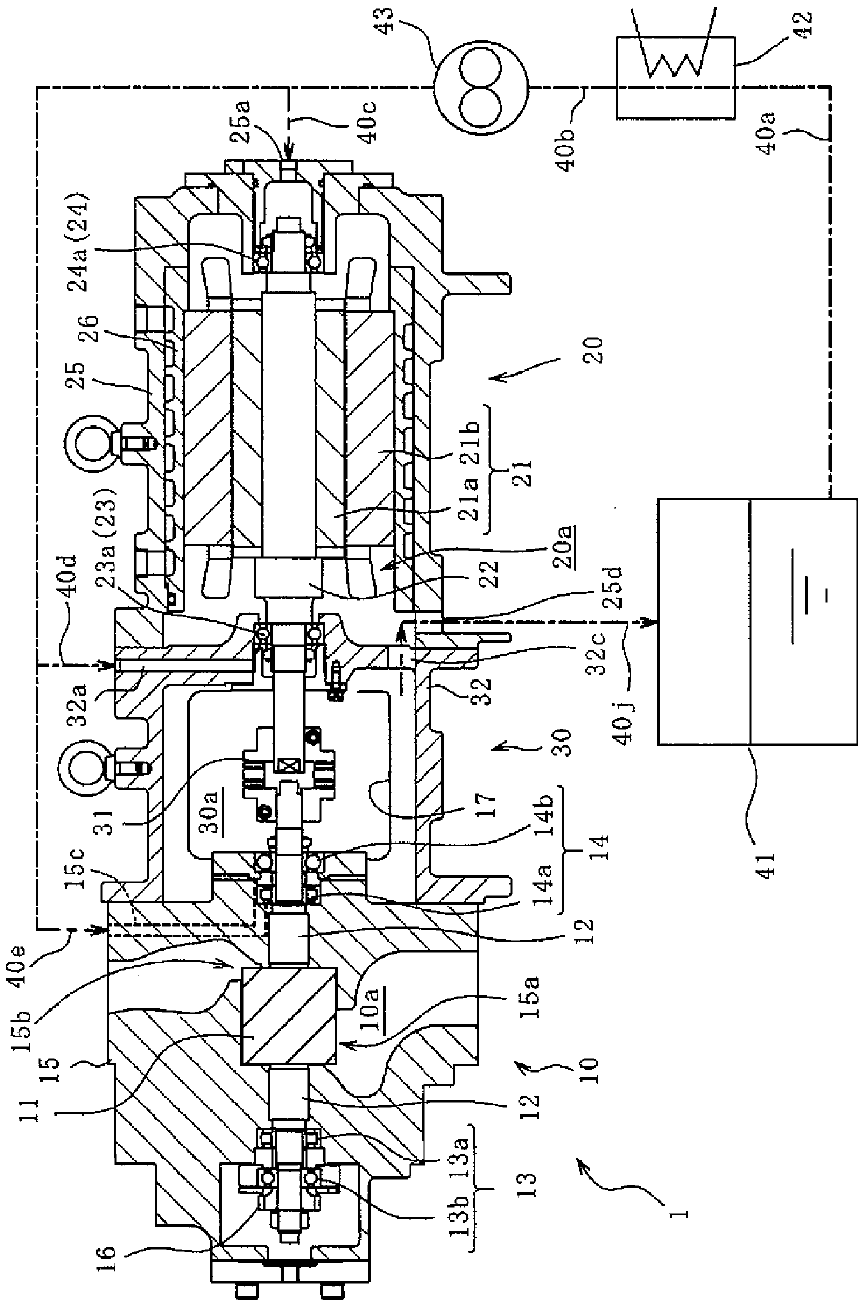
[0027] like figure 1 As shown, the oil-free screw compressor 1 is provided with the compression part 10 in which the screw rotor 11 is arranged, the motor part 20 in which the motor 21 is arranged, and the connection part 30 which connects these. The oil-free screw compressor 1 is driven by the motor 21 of the motor section 20 to drive the screw rotor 11 of the compression section 10 to suck, compress, and discharge gas.
[0028] The compression unit 10 includes a male and female screw rotor 11 having a rotor shaft 12, a first bearing 13 and a second bearing 14 that support both ends of the rotor shaft 12, and a rotor casing 15 that accommodates these and defines the rotor chamber 10a. .
[0029] The screw rotor 11 has a female rotor and a male rotor, which mesh with each other in the rotor chamber 10a in a state of no oil supply, thereby compressing the gas. exist figure 1 The male rotor and its rotor shaft 12 are shown, but there are rotor shafts 12 on the male and female...
no. 2 Embodiment approach )
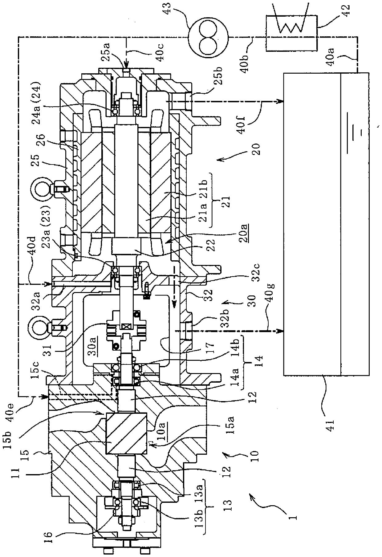
[0056] image 3 The oil-free screw compressor 1 of the second embodiment is shown. In this embodiment, the same reference numerals are assigned to the same components as those in the first embodiment, and description thereof will be omitted.
[0057] In this embodiment, the communication part 32c is a member which makes the lubricating oil lubricated by the 2nd bearing 14 flow from the connection chamber 30a to the motor chamber 20a. That is, the flow direction of the lubricating oil in the communicating portion 32c is different from that of the first embodiment. However, as in the first embodiment, the communication portion 32c is a simple through hole, and the flow direction of lubricating oil in the communication portion 32c is limited by the difference between the flow pressure generated by the oil pump 43 and the internal pressure of the oil tank 41 .
[0058] In addition, in this embodiment, instead of the second oil discharge port 32b of the first embodiment (refer to...
no. 3 Embodiment approach )
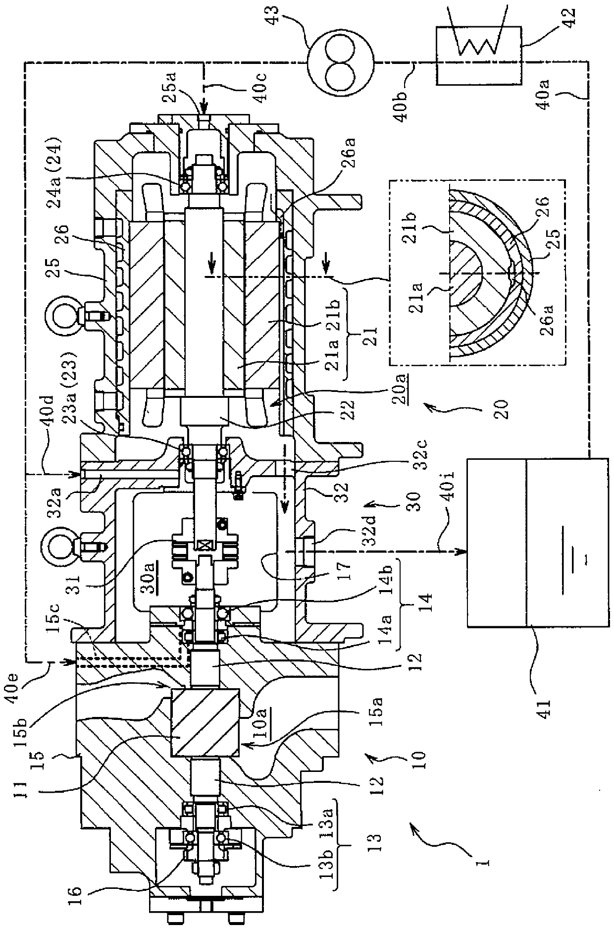
[0061] Figure 4 An oil-free screw compressor 1 according to a third embodiment is shown. In this embodiment, the same reference numerals are assigned to the same components as those in the first embodiment, and description thereof will be omitted.
[0062] In this embodiment, unlike the first embodiment, the first oil discharge port 25b is not provided on the motor case 25 (refer to figure 1 ) and oil line 40f (refer to figure 1 ). That is, instead of directly sending the lubricating oil from the motor chamber 20a to the oil tank 41, all the lubricating oil in the motor chamber 20a flows into the connection chamber 30a through the communicating portion 32c. Therefore, in this embodiment, the oil guide groove 26a for guiding the lubricating oil lubricated by the 4th bearing 24 to the communication part 32c is formed especially. as in Figure 4 As shown in detail in the sectional view in , the oil guide groove 26a is a groove formed on the inner surface of the bottom of th...
PUM
 Abstract
Description
Claims
Application Information