Oil collector for hydraulic oil tank of roll bending hydraulic station

A technology of hydraulic oil tank and oil collecting device, which is applied in the direction of oil supply oil tank device, metal rolling, metal rolling rack, etc. It can solve the problems of flowing to the ground and the difficulty of hydraulic oil in the oil tank getting into the oil barrel, etc., and achieves relief The workload, the structure is simple, and the effect of avoiding oil accumulation

Inactive Publication Date: 2010-07-21
WUXI WUYE METAL ROLLING
View PDF0 Cites 0 Cited by
  • Summary
  • Abstract
  • Description
  • Claims
  • Application Information

AI Technical Summary

Problems solved by technology

Although the oil tank can collect the hydraulic oil leaked from the hydraulic valve block or pipeline system, another problem is found in actual use. The hydraulic oil in the oil tank is difficult to get into the oil barrel, and sometimes the hydraulic oil in the oil tank If the oil is too late to clean up, it will flow to the ground

Method used


Image

  • Oil collector for hydraulic oil tank of roll bending hydraulic station
  • Oil collector for hydraulic oil tank of roll bending hydraulic station
  • Oil collector for hydraulic oil tank of roll bending hydraulic station

Examples


Embodiment Construction

[0010] Below the present invention will be further described in conjunction with the embodiment in the accompanying drawing:

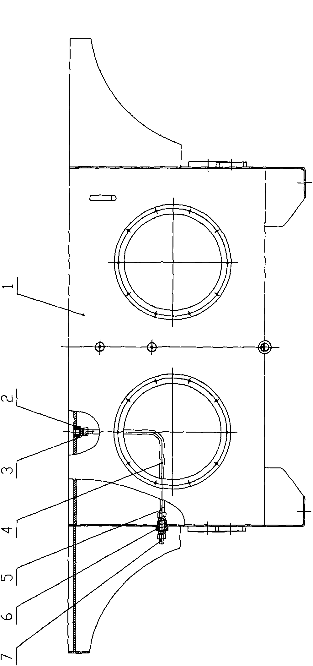
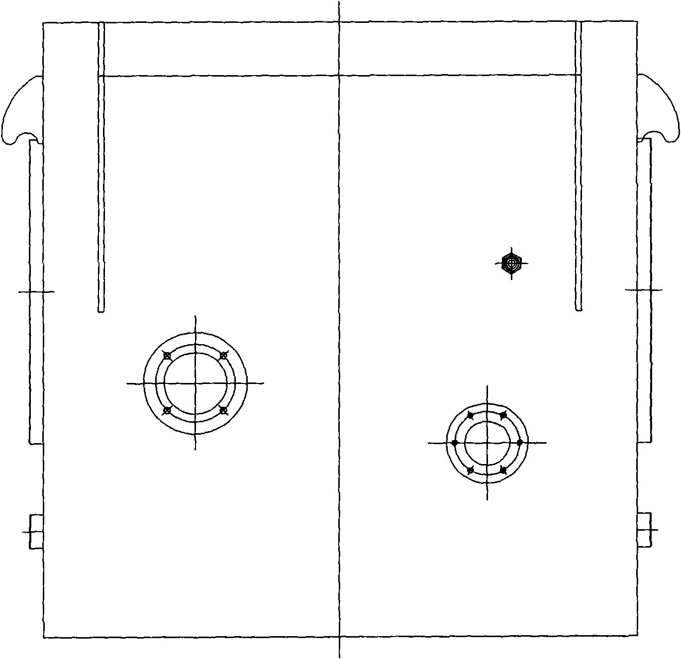
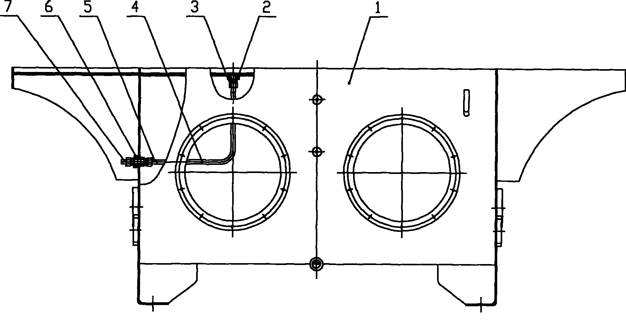
[0011] Such as Figure 1 ~ Figure 2 As shown, it includes a hydraulic oil tank 1 , an internal thread joint 2 , a first straight joint 3 , a steel pipe 4 , a second straight joint 5 , a joint body 6 and a third straight joint 7 .

[0012] The present invention adopts the hole of drilling a φ 35 on the lower left side of the hydraulic oil tank 1 top plate; As shown in the left view, also drill a φ 35 hole in the right side middle part of this view. Weld an internal thread joint 2 on the top of the hydraulic oil tank 1 and weld a joint body 6 on the side of the hydraulic oil tank 1 to facilitate the installation of hydraulic pipe joints; the steel pipe 4 Bend to 90 degrees, weld the first straight joint 3 and the second straight joint 5 on both sides of the steel pipe 4 respectively, the first straight joint 3 and the second straight joint 5 are install...


PUM


Abstract

The invention relates to an oil collector for a hydraulic oil tank of a six-roller cold mill hydraulic system. The oil collector comprises a hydraulic oil tank, an internal thread joint, a first through joint, a steel tube, a second through joint, a joint body and a third through joint. The internal thread joint is welded on the top of the hydraulic oil tank. The joint body is welded on the side face of the hydraulic oil tank so as to facilitate arranging a hydraulic tube joint. The steel tube is bent into 90 degrees, and the first through joint and the second through joint are welded on two sides of the steel tube respectively. The first through joint and the second through joint are welded on the top and on the side face of the hydraulic oil tank respectively. The third through joint is also arranged outside the joint body on an external plate of the hydraulic oil tank, so that the hydraulic oil on the top of the oil tank is led to an oil drum. The oil collector for the hydraulic oil tank has the advantages of avoiding oil accumulation on the top of the oil tank, easily leading the hydraulic oil into the oil drum and lightening the workload for system maintenance, along with simple, compact and reasonable structure.

Description

technical field [0001] The invention relates to an oil collecting device of a hydraulic oil tank, which is used for the oil collecting device of the hydraulic oil tank of the hydraulic system of a six-roll cold rolling mill. Background technique [0002] The roll bending hydraulic station is an integral structure, the motor and all hydraulic components are installed on the hydraulic oil tank, and the main valve block of the system is installed on the top of the hydraulic oil tank. When designing the hydraulic oil tank, in order to facilitate the maintenance and inspection of the entire system, a concave oil tank is designed on the top of the hydraulic oil tank to collect leakage from the hydraulic valve block or piping system when the inspection equipment and seal fail. Hydraulic oil. Although the oil tank can collect hydraulic oil leaked from the hydraulic valve block or pipeline system, another problem has been found in actual use. The hydraulic oil in the oil tank is dif...

Claims


Application Information

Patent Timeline
IPC IPC(8): F15B1/26B21B31/32
Inventor 周小萍
Owner WUXI WUYE METAL ROLLING
Why Eureka
Try Eureka