Supercharge Your Innovation With Domain-Expert AI Agents!

Light emitting device package with reflective side coating

A light-emitting device and side-covering technology, which is applied in the direction of semiconductor devices, electrical components, circuits, etc.

Active Publication Date: 2019-06-04
LUMILEDS
View PDF6 Cites 2 Cited by
  • Summary
  • Abstract
  • Description
  • Claims
  • Application Information

AI Technical Summary

Problems solved by technology

[0007] The present disclosure addresses this need

Method used


Image

  • Light emitting device package with reflective side coating
  • Light emitting device package with reflective side coating
  • Light emitting device package with reflective side coating

Examples


Embodiment Construction

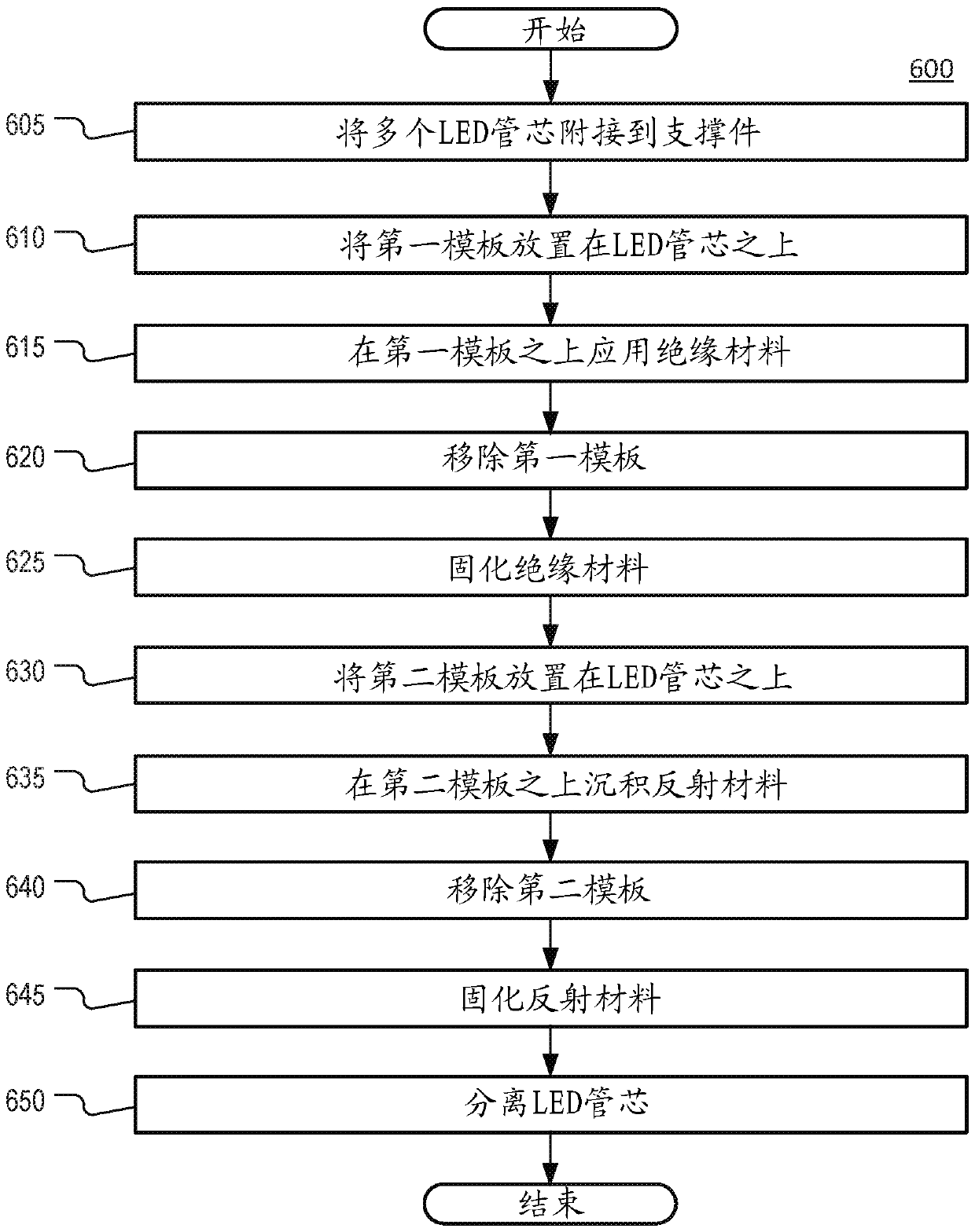
[0031] According to aspects of the present disclosure, a light emitting device is disclosed that includes a light emitting semiconductor structure and a wavelength converter formed over the semiconductor structure. The semiconductor structure is at least partially surrounded by an insulating lateral cladding. The wavelength converter is at least partially surrounded by a reflective side cladding formed on top of the insulating side cladding. Because the reflective cladding is in thermal contact with the wavelength converter, the reflective side cladding provides another path for heat transfer from the wavelength converter to the surrounding environment.

[0032] According to aspects of the present disclosure, the reflective side coating can help protect the wavelength converter from overheating. In general, overheating can cause the color shift of the wavelength converter and shorten its lifetime. By efficiently directing heat away from the wavelength converter, reflective s...


PUM

PropertyMeasurementUnit
Thermal conductivityaaaaaaaaaa

Abstract

A light-emitting device is disclosed that includes a semiconductor structure having an active region disposed between an n-type layer and a p-type layer; a wavelength converter formed above the semiconductor structure; an insulating side coating formed around the semiconductor structure; and a reflective side coating formed around the wavelength converter above the insulating side coating, the reflective side coating having a top surface that is flush with a top surface of the wavelength converter.

Description

[0001] Cross References to Related Applications [0002] This application claims U.S. Provisional Application No. 62 / 368067, filed July 28, 2016, European Patent Application No. 16190895.9, filed September 27, 2016, and U.S. Non-Provisional Application No. 15 / 661196, these applications are incorporated by reference as if fully set forth. technical field [0003] The present disclosure relates generally to light emitting devices, and more particularly, to light emitting device packages having reflective side cladding. Background technique [0004] Light emitting diodes ("LEDs") are commonly used as light sources in a variety of applications. The main functional part of an LED may be a semiconductor chip comprising two injection layers of opposite conductivity types (p-type and n-type) and a light-emitting active layer where radiative recombination of carrier injection takes place. The semiconductor chip is usually placed in a package which, in addition to protecting the sem...

Claims


Application Information

Patent Timeline
IPC IPC(8): H01L33/50H01L33/64H01L33/56H01L33/54H01L33/60H01L33/48
CPCH01L33/502H01L33/46H01L33/644H01L33/56H01L33/642H01L33/10H01L33/60H01L33/507H01L33/486H01L2933/005H01L2933/0075H01L2933/0041
Inventor R-C.刘T-Y.显
Owner LUMILEDS
Features
  • R&D
  • Intellectual Property
  • Life Sciences
  • Materials
  • Tech Scout
  • Unparalleled Data Quality
  • Higher Quality Content
  • 60% Fewer Hallucinations
Learn More