Hydraulic gear grinding clamp

A fixture and hydraulic technology, applied in the direction of gear teeth, gear cutting machines, manufacturing tools, etc., can solve the problems of wasting manpower, long clamping operation time, gear skew, etc., and achieve the effect of efficient positioning and easy oil filling operation.

Pending Publication Date: 2019-06-07
定州市新华机械制造有限公司
View PDF0 Cites 6 Cited by
  • Summary
  • Abstract
  • Description
  • Claims
  • Application Information

AI Technical Summary

Problems solved by technology

[0004] The technical problem to be solved in the present invention is to provide a hydraulic gear grinding fixture to solve the problems of long manual clamping operation of the gear, prone to gear deviation and waste of a lot of manpower, so as to achieve accurate and rapid positioning of the gear , to meet the high-precision processing requirements of gears

Method used


Image

  • Hydraulic gear grinding clamp
  • Hydraulic gear grinding clamp

Examples


Embodiment Construction

[0023] The present invention will be further described in detail in conjunction with specific inventions below.

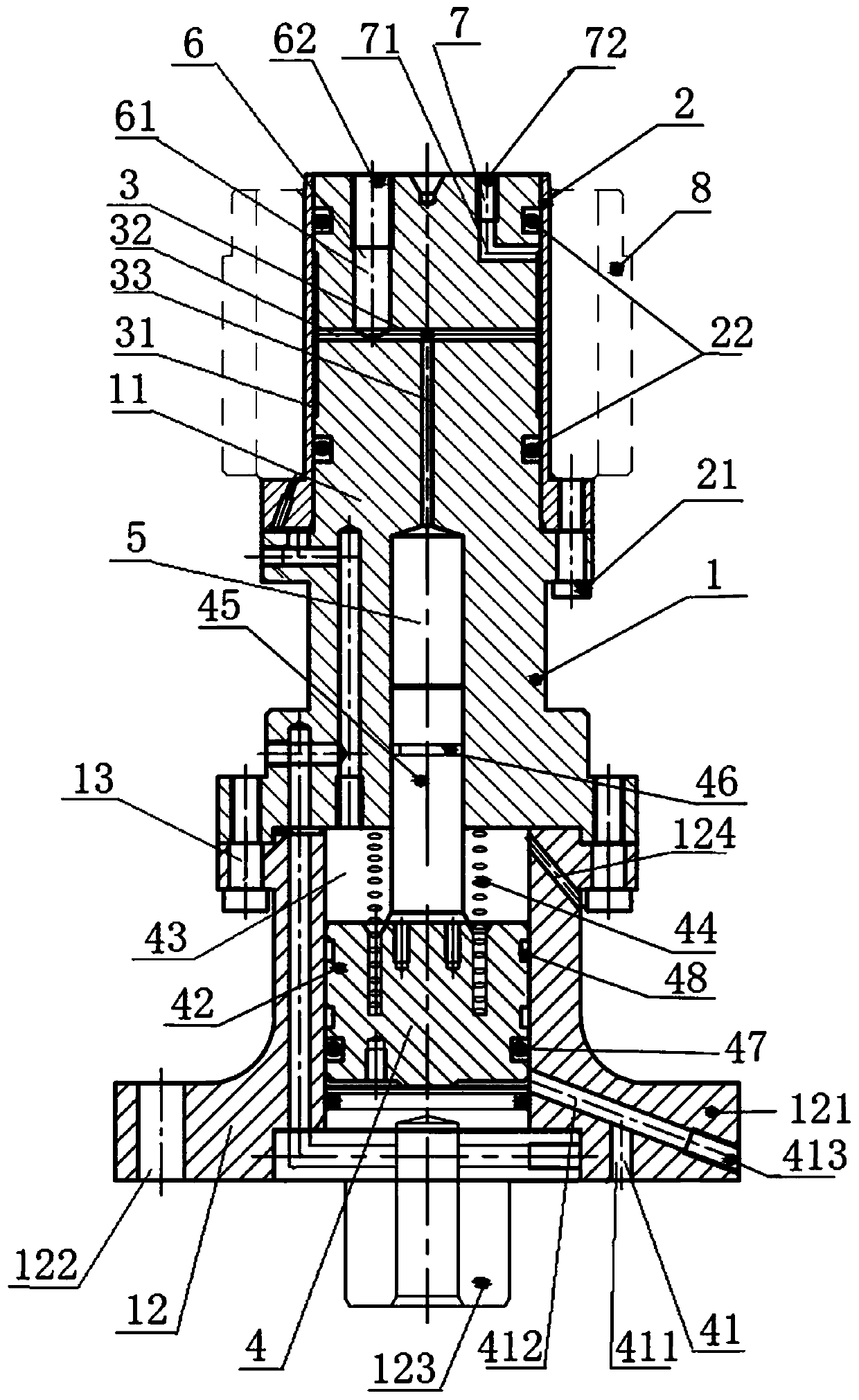
[0024] A hydraulic gear grinding fixture, combined with figure 1 As shown, it includes a clamp body 1 , an elastic sleeve 2 , an upper oil storage chamber 5 , an elastic sleeve tightening oil passage 3 and a hydraulic drive structure 4 .

[0025] The fixture body 1 is divided into a fixture upper body 11 and a fixture lower body 12 , and the fixture upper body 11 and the fixture lower body 12 are fixedly connected by hexagon socket bolts 13 . The lower part of the fixture lower body 12 is provided with a base 121, and the middle part of the base 121 is provided with a positioning shaft 123, and the positioning shaft 123 is used for inserting the fixture body 1 into the gear grinding machine workbench to realize the positioning of the fixture body 1. A connecting hole 122 is opened on the base 121, and the connecting hole 122 is used for passing a bolt to fix the f...


PUM


Abstract

The invention discloses a hydraulic gear grinding clamp. The clamp comprises a clamp body, wherein the clamp body is divided into an upper clamp body and a lower clamp body that are fixedly connected;an elastic sleeve for sleeving and positioning the inner hole of a gear to be machined seals and sleeves around the upper outer wall of the upper clamp body; an upper oil storage cavity for storing hydraulic oil is arranged inside the upper clamp body; an elastic-sleeve tension oil passage that communicates with the upper oil storage cavity and is partially arranged between the outer wall of theupper clamp body and the inner wall of the elastic sleeve is also arranged inside the upper clamp body; and a hydraulic drive structure for pressing the hydraulic oil in the upper oil storage cavity into the elastic-sleeve tension oil passage and further pressing the hydraulic oil into between the outer wall of the upper clamp body and the inner wall of the elastic sleeve is arranged on the lowerclamp body. According to the hydraulic gear grinding clamp, the gear to be machined can be sleeved with the elastic sleeve, and the hydraulic drive structure drives the hydraulic oil in the upper oilstorage cavity to flow into the elastic-sleeve tension oil passage and then press the elastic sleeve, so that the elastic sleeve positions the inner hole of the gear.

Description

technical field [0001] The invention relates to the technical field of gear processing and manufacturing, in particular to a hydraulic gear grinding fixture. Background technique [0002] Grinding is a process of processing cylindrical gears or certain gears (helical gears, bevel gears, etc.) using abrasive tools such as grinding wheels. It is mainly used to eliminate deformation after heat treatment and improve gear accuracy. Gear grinding machine is a metal cutting machine tool for gear finishing. It uses a grinding wheel as a tool to grind the gear tooth surface that has been processed to improve the precision and surface finish of the gear. It is suitable for finishing and quenching with high hardness. Steel gears. When in use, the fixture is used to clamp the part, and the machine tool performs processing according to the set program. [0003] When the existing gears are being grinded, they are usually manually aligned and clamped, that is, the inner hole runout is me...

Claims


Application Information

Patent Timeline
Patent Type & Authority Applications(China)
IPC IPC(8): B23F23/06
Inventor 李伟王庆彬刘保健
Owner 定州市新华机械制造有限公司
Why Eureka
Try Eureka