
Lateral positioning device

A technology of lateral positioning and positioning holes, which is applied in the directions of positioning devices, clamping, and supports, can solve the problems of inability to position laterally, and achieve the effects of low manufacturing cost, simple structure and convenient manufacturing.

Inactive Publication Date: 2019-06-07
扬州添博汽车工装有限公司
View PDF0 Cites 1 Cited by
  • Summary
  • Abstract
  • Description
  • Claims
  • Application Information

AI Technical Summary

Problems solved by technology

Some existing positioning devices can only perform point positioning and cannot perform side positioning

Method used


Image

  • Lateral positioning device

Examples


Embodiment Construction

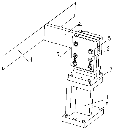
[0013] A lateral positioning device, comprising a base 1, a connecting frame 2 and a rotating plate 3, the front end of the rotating plate 3 is fixedly mounted with a lateral positioning plate 4, the connecting frame 2 is fixedly mounted on the upper end of the base 1, and the connecting frame 2 It is a U-shaped frame, and the end of the rotating plate 3 is located in the U-shaped groove of the connecting frame 2. The end of the rotating plate 3 is provided with a through hole, and the through hole of the rotating plate 3 is rotatably connected with the connecting frame 2 by bolts 5.

[0014] As a further improvement of the above technical solution, the rotating plate 3 is provided with a positioning hole located on the front side of the through hole, the connecting frame 2 is provided with a locking hole matching the positioning hole, and the positioning hole and the locking hole pass through the locking pin 6 connections.

[0015] As a further improvement of the above techni...


PUM


Abstract

The invention relates to a lateral positioning device. The device comprises a base, a connecting frame and a rotating plate; a lateral positioning plate is fixedly mounted on the front end of the rotating plate, the connecting frame is fixedly mounted on the upper end of the base, the connecting frame is U frame, the tail end of the rotating plate is located in a U groove of the connecting frame,a through hole is formed in the tail end of the rotating plate, the through hole of the rotating plate is rotatably connected with the connecting frame. The lateral positioning device is simple in structure, convenient to manufacture and low in manufacturing cost, the lateral positioning plate is added on the front end of the rotating plate, the object can be laterally positioned, and lateral positioning of the object is achieved.

Description

technical field [0001] The invention relates to a positioning device, in particular to a lateral positioning device. Background technique [0002] Tooling fixture refers to the tool used to quickly fasten the workpiece in the manufacturing process and the process device to keep the workpiece in the correct relative position. It is an indispensable part of mechanical processing. Driven by the development of environmental protection, fixture technology is developing in the direction of high precision, high efficiency, modularity, combination, general purpose and economy. Some existing positioning devices can only perform point positioning, but cannot perform side positioning. Contents of the invention [0003] In view of the above defects, the object of the present invention is to provide a side positioning device which is simple in structure, easy to operate, low in manufacturing cost and capable of side positioning of objects. [0004] The technical scheme that the prese...

Claims


Application Information

Patent Timeline
IPC IPC(8): B23Q3/18
Inventor 俞芳芳
Owner 扬州添博汽车工装有限公司
Learn More