Mechanical arm joint with controllable rigidity

A technology of robotic arms and joints, applied in the field of robotics, can solve the problems of low motion accuracy, inconvenient control, complex structure, etc.

Active Publication Date: 2019-06-07
SHANGHAI UNIV OF ENG SCI
View PDF8 Cites 2 Cited by
  • Summary
  • Abstract
  • Description
  • Claims
  • Application Information

AI Technical Summary

Problems solved by technology

[0004] The purpose of the present invention is to provide a mechanical arm joint with controllable stiffness, which overcomes the defects of complex structure, inconvenient control and low motion precision in the prior art

Method used


Image

  • Mechanical arm joint with controllable rigidity
  • Mechanical arm joint with controllable rigidity

Examples


Embodiment

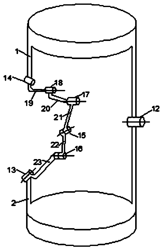
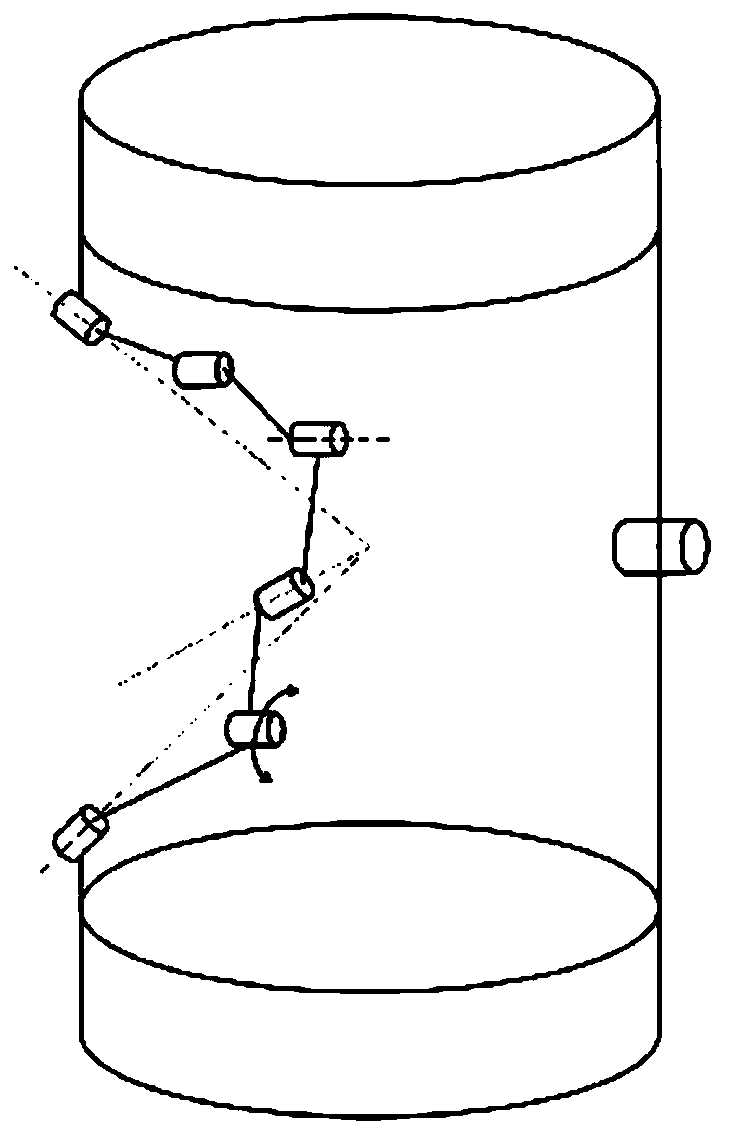
[0027] A manipulator joint with controllable stiffness, its structure is as follows figure 1 As shown, it includes an upper platform 1, a lower platform 2, and a first kinematic branch chain and a second kinematic branch chain connected between the upper platform and the lower platform.

[0028] The first kinematic branch chain includes a first revolving pair 13, a second revolving pair 16, a third revolving pair 15, a fourth revolving pair 17, a fifth revolving pair 18 and a sixth revolving pair 14; the sixth revolving pair 14, the seventh revolving pair The swivel pair 12 is connected with the upper platform 1 , and the first swivel pair 13 and the seventh swivel pair 12 are connected with the lower platform 2 . The second kinematic branch chain includes the fifth and seventh revolving pairs 16; the fifth revolving pair 18 is connected with the first revolving pair 14 through the first connecting rod 19, and the fifth revolving pair 18 is connected with the sixth revolving p...


PUM


Abstract

The invention provides a mechanical arm joint with controllable rigidity. The mechanical arm joint comprises an upper platform, a lower platform, and a first motion branched chain and a second motionbranched chain connected between the platforms. The first motion branched chain comprises six rotating pairs; a sixth rotating pair and a seventh rotating pair are connected with the upper platform; afirst rotating pair is connected with a second rotating pair through a connecting rod; the second rotating pair is connected with a third rotating pair through a connecting rod; the third rotating pair is connected with a fourth rotating pair through a connecting rod; the fourth rotating pair is connected with a fifth rotating pair through a connecting rod; the fifth rotating pair is connected with the sixth rotating pair through a connecting rod; the second motion branched chain comprises the seventh rotating pair; and the seventh rotating pair is connected with the upper platform and the lower platform. The second rotating pair is driven to change the axis position of the third rotating pair, so that the position of an intersecting point of the axis of the first rotating pair, the axisof the third rotating pair and the axis of the sixth rotating pair in movement of the first branched chain is changed, rotating conditions are destructed, and the rigidity controllability of the mechanism and the locking in any position are achieved.

Description

technical field [0001] The invention relates to the field of robots, in particular to a mechanical arm joint with controllable stiffness. Background technique [0002] The robotic arm is a bionic electromechanical device that can simulate human hand movements to achieve operations by changing the pose of the target object. Widely used in large-scale equipment, robots, sensors and micro-operation fields. To maintain a specified position and posture in space, the joints of the robot must be locked in a given posture, so the joint locking of the robot has become an indispensable part of the robot mechanism design. However, most of the mechanical arm joints realize the movement of the mechanism through the rotating shaft. When it stops working, due to inertia and other reasons, it may still cause a small amount of relative rotation between the two components. Therefore, a mechanical mechanism that can realize its self-locking is designed. Joints, improving motion precision is ...

Claims


Application Information

Patent Timeline
Patent Type & Authority Applications(China)
IPC IPC(8): B25J17/00B25J9/00
Inventor 张帆陈龙凯崔国华张丹孙晶郑民华潘睿俊
Owner SHANGHAI UNIV OF ENG SCI
Why Eureka
Try Eureka