Electric power-assisted braking system

A brake system and electric power assist technology, applied in brakes, brake transmissions, transportation and packaging, etc., can solve problems such as potential safety hazards in the brake system, improve sensor accuracy, achieve gear meshing frequency, and increase the number of large gear teeth Effect

Active Publication Date: 2019-06-07
SHANGHAI HUIZHONG AUTOMOTIVE MFG
View PDF8 Cites 1 Cited by
  • Summary
  • Abstract
  • Description
  • Claims
  • Application Information

AI Technical Summary

Problems solved by technology

[0008] The technical problem to be solved by the present invention is to provide an electric power-assisted braking system in order to overcome the defect that the braking system in the prior art is likely to cause safety hazards

Method used


Image

  • Electric power-assisted braking system
  • Electric power-assisted braking system

Examples


Embodiment Construction

[0034] In order to make the above objects, features and advantages of the present invention more comprehensible, specific implementations of the present invention will be described in detail below in conjunction with the accompanying drawings.

[0035] Embodiments of the present invention will now be described in detail with reference to the accompanying drawings. Reference will now be made in detail to the preferred embodiments of the invention, examples of which are illustrated in the accompanying drawings. Wherever possible, the same numbers will be used throughout the drawings to refer to the same or like parts.

[0036] In addition, although the terms used in the present invention are selected from well-known and commonly used terms, some terms mentioned in the description of the present invention may be selected by the applicant according to his or her judgment, and the detailed meanings thereof are set forth herein described in the relevant section of the description. ...


PUM


Abstract

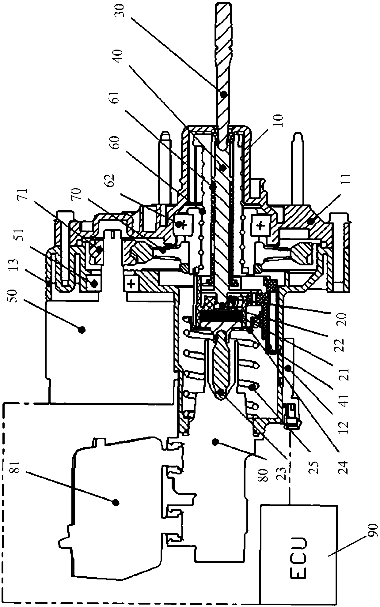
The invention provides an electric power-assisted braking system that comprises a power booster outer shell; a power assisting sleeve is arranged in the power booster outer shell; one end of a brake pedal push rod penetrates into one end of the power booster outer shell and is hinged to one end of a booster push rod. The booster push rod is installed at one end of the power assisting sleeve and can move in the power assisting sleeve; a motion conversion mechanism is mounted outside the booster push rod, is connected with a motor and used for realizing conversion from rotation to translation ofthe motor. According to the electric power-assisted braking system, conversion from rotation to translation of the motor is achieved through a gear reduction mechanism, and then a transmission targetis achieved through a hollow ball screw mechanism. By reducing the number of teeth of a pinion and increasing the number of teeth of a bull gear, the meshing frequency of the gears is reduced, meanwhile, the linear speed of the ball screw is reduced, and the NVH performance is improved.

Description

technical field [0001] The invention relates to the field of automobile braking systems, in particular to an electric power-assisted braking system. Background technique [0002] With the development of electric vehicles and smart vehicles, new requirements are put forward for the braking system, such as the ability to independently generate the required braking force (active braking), to realize the function of braking energy recovery, and to be able to match the active safety system of the chassis. Function. For example, anti-lock braking system (ABS, Anti-lock Braking System), driving anti-skid control (ASR, Acceleration Skid control system), vehicle stability control system (ESC, Electronic Stability controller) and adaptive cruise control (ACC, Adaptive Cruise Control) etc. [0003] The traditional hydraulic braking system uses a vacuum booster and a master cylinder and wheel cylinder system. Among them, the vacuum booster needs to draw vacuum through the engine. Ho...

Claims


Application Information

Patent Timeline
Patent Type & Authority Applications(China)
IPC IPC(8): B60T13/74
Inventor 邹常华翟林铎李宏伟李向杨凯寅
Owner SHANGHAI HUIZHONG AUTOMOTIVE MFG
Why Eureka
Try Eureka