Speed reducer assembly and vehicle provided with same

A reducer and assembly technology, which is applied in the vehicle reducer assembly and the vehicle field with the reducer assembly, can solve the problems that the loss of spline meshing force transmission energy cannot be eliminated, and the cost of the motor and rear axle is high. Achieve the effect of reducing power transmission path, reducing unsprung mass and increasing transmission efficiency

Inactive Publication Date: 2019-12-13
SHAANXI AUTOMOBILE GROUP +1
View PDF6 Cites 1 Cited by
  • Summary
  • Abstract
  • Description
  • Claims
  • Application Information

AI Technical Summary

Problems solved by technology

[0005] 3. Spline meshing force transmission can not eliminate the energy loss;
[0006] 4. Problems such as high cost of motor and rear axle cannot be solved

Method used


Image

  • Speed reducer assembly and vehicle provided with same

Examples


Embodiment 1

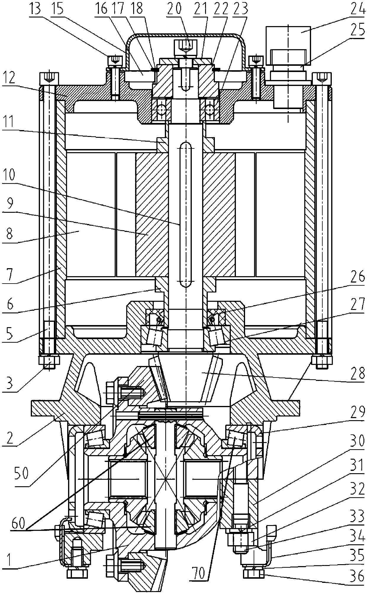
[0031] Such as figure 1 Shown is a schematic structural diagram of the reducer assembly in Embodiment 1 of the present invention. Embodiment 1 of the present invention provides a reducer assembly, which includes a motor assembly, a differential assembly 1 and a driving wheel shaft 10, the motor assembly is connected to the differential assembly 1 through the driving wheel shaft 10, and sends into 1 drive. The motor assembly is connected with the driving wheel shaft 10, and the motor assembly drives the driving wheel shaft 10 to rotate.

[0032] One end of the driving wheel shaft 10 is provided with a driving gear 28 , the driving gear 28 meshes with the driven gear 50 in the differential assembly 1 , and the driving gear 28 is used to transmit to the driven gear 50 in the differential assembly 1 . Preferably the drive gear 28 is a bevel gear. Preferably, the axis of the driving wheel shaft 10 coincides with the axis of the motor assembly.

[0033] The motor assembly includ...

Embodiment 2

[0045] The difference between this embodiment and Embodiment 1 is that an adjustment device is also provided on the differential assembly 1, and the adjustment device can drive the differential body to move axially and laterally to adjust the gears of the driving gear 28 and the driven gear 50 Fit clearance. The adjusting device is preferably an adjusting screw.

Embodiment 3

[0047] The difference between this embodiment and Embodiment 2 is that a differential bearing 70 is also arranged on the differential assembly 1, and the differential bearing 70 is arranged at both ends of the differential body, and the inside of the differential bearing 70 Circles can be used to traverse either the left or right half shaft. The axis of the differential bearing 70 is the same as the left half shaft or the right half shaft. The adjusting device is an adjusting screw ring 29 , and the adjusting screw ring 29 drives the differential body to move axially and laterally through the differential bearing 70 to adjust the gear fit clearance between the driving gear 28 and the driven gear 50 .


PUM


Abstract

The invention relates to the technical field of speed reducers and provides a speed reducer assembly which comprises a motor component, a differential mechanism assembly and a drive wheel axle, wherein the motor component is connected with the drive wheel axle and drives the drive wheel axle to rotate; a driving gear is arranged on the drive wheel axle, is meshed with a driven gear on the differential mechanism assembly and drives the differential mechanism assembly; and the differential mechanism assembly drives a left half axle and/or a right half axle. The invention further provides a vehicle. The vehicle comprises a vehicle body and the speed reducer assembly, wherein the speed reducer assembly is arranged on the vehicle body and is further connected with a vehicle half axle. Comparedwith the prior art, the speed reducer assembly has the following benefits: the speed reducer assembly is suitable for an electric vehicle; the speed reducer and a motor are integrated, so that the assembling link of the motor and the speed reducer is reduced, the unsprung mass of the finished vehicle is reduced, the power driving way is reduced, the transmission efficiency is improved, and the effects of the light vehicle body, energy conservation and emission reduction are realized.

Description

technical field [0001] The invention relates to the technical field of speed reducers, in particular to a speed reducer assembly for a vehicle and a vehicle with the speed reducer assembly. Background technique [0002] With the development of science and technology, clean new energy has become the mainstream trend in the world, and new energy vehicles have emerged as the times require. With the development of new energy vehicles, issues related to the increase in mileage of new energy vehicles, manufacturing costs, lightweight layout of vehicle chassis, and noise control have begun to attract people's attention, which is also the bottleneck of the development of new energy vehicles at this stage. Most of them use the direct connection structure between the rear axle and the motor, and transmit power through seam positioning, bolt connection and spline engagement. In the design process of the new energy vehicle chassis, there are certain disadvantages in adopting this struc...

Claims


Application Information

Patent Timeline
Patent Type & Authority Applications(China)
IPC IPC(8): B60K1/00B60K17/16H02K7/116
CPCB60K1/00B60K17/16H02K7/116
Inventor 景浩旭赵亚鹏卜娟张稳张瑞青
Owner SHAANXI AUTOMOBILE GROUP
Why Eureka
Try Eureka