Novel elevator traction system

A new type of elevator traction technology, which is applied to elevators, elevators, transportation and packaging in buildings, etc. It can solve the problems of short service life and high maintenance costs of traction ropes or traction belts, and achieve maintenance cost savings and weight reduction Requirements, the effect of reducing product costs

Pending Publication Date: 2019-06-07
GIANT KONE ELEVATOR CO LTD
View PDF6 Cites 2 Cited by
  • Summary
  • Abstract
  • Description
  • Claims
  • Application Information

AI Technical Summary

Problems solved by technology

[0004] The purpose of the present invention is to make up for the defects existing in the prior art, provide a new type of elevator traction system, and solve the problem of the life of the traction rope or traction belt in the elevator traction system that uses pressure rollers to apply pressure to the traction rope or traction belt. Short, requires frequent repairs and replacements, and high maintenance costs

Method used


Image

  • Novel elevator traction system
  • Novel elevator traction system
  • Novel elevator traction system

Examples


Embodiment Construction

[0020] The specific implementation manner of the present invention will be briefly described below in conjunction with the accompanying drawings.

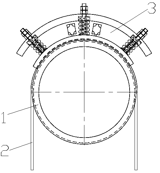
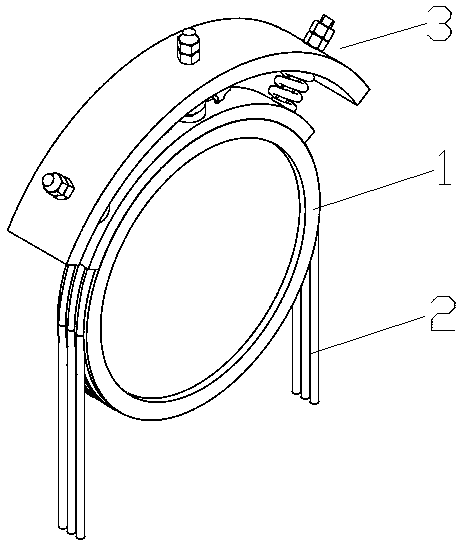
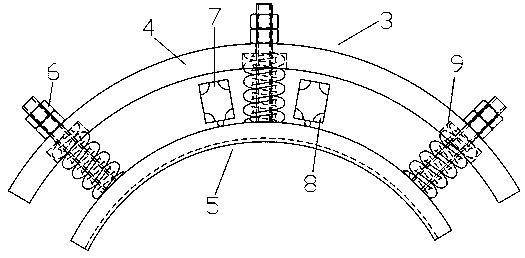
[0021] Such as Figure 1-4 As shown, the new elevator traction system includes a traction wheel 1 and a traction rope or traction belt 2 wound on the traction wheel 1, and also includes a At least one pressure loading assembly 3, the pressure loading assembly 3 includes an arc-shaped support frame 4 and an adjustable pressure plate assembly 5 installed on the support frame 4, the support frame 4 and the traction The wheels 1 are concentrically arranged and their relative positions are fixed. The adjustable pressure plate assembly 5 includes an arc-shaped pressure plate 10, a plurality of installation rods 11 and a plurality of compressed elastic elements 12, each of the plurality of elastic elements 12 is respectively Sleeved on a corresponding one of the plurality of installation rods 11, the lower ends of the plurality of instal...


PUM


Abstract

The invention discloses a novel elevator traction system, and relates to the field of elevators. The novel elevator traction system comprises a traction wheel, and a traction rope or a traction belt wound on the traction wheel. The novel elevator traction system further comprises at least one pressure loading module arranged above the traction rope or the traction belt; the pressure loading modulecomprises an arc support frame, and an adjustable pressure plate module mounted on the support frame; the adjustable pressure plate module comprises an arc pressing plate, multiple mounting rods andmultiple compressed elastic elements; the lower ends of the multiple mounting rods are fixedly connected with the upper surface of the pressing plate; the upper ends of the multiple mounting rods aremounted on the support frame; the lower ends of the elastic elements abut against the upper surface of the pressing plate; the upper ends of the elastic elements abut against the support frame; the lower surface of the pressing plate is bonded with the traction rope or the traction belt to load pressure pointed to the axis of the traction wheel; and the upper ends of the multiple mounting rods canbe telescopically adjusted in the radial direction of the support frame to adjust the pressure loaded by the pressing plate. The novel elevator traction system has no need of frequent maintenance andreplacement, and saves the maintenance cost.

Description

technical field [0001] The invention relates to the field of elevators, in particular to a novel elevator traction system. Background technique [0002] For the traditional elevator traction system, the traction wire rope or traction steel belt passes through the tension on both sides to generate friction on the traction sheave, thereby driving the elevator to run up and down. With the development of lightweight elevator cars, it is usually necessary to increase the weight of the counterweight on the car side and the weight on the counterweight side to ensure the traction capacity of the elevator system, which greatly increases the cost of the elevator. In addition, the role of changing the traction capacity by changing the groove angle of the traction sheave, such as U-shaped groove or V-shaped groove, or changing the groove angle is relatively limited, and the processing requirements are high. [0003] An optional way is to set a pressure loading device, and apply pressur...

Claims


Application Information

Patent Timeline
Patent Type & Authority Applications(China)
IPC IPC(8): B66B11/08B66B5/00
Inventor 杨佳民叶佳芳叶仁杰冯骏豪
Owner GIANT KONE ELEVATOR CO LTD
Why Eureka
Try Eureka