
Offshore wind power combination foundation

A combined foundation and offshore wind power technology, applied in infrastructure engineering, construction, etc., can solve the problems of increasing foundation cost and construction period, main leg distance and steel pipe pile length, and increasing wave load, so as to improve the anti-overturning ability. , The effect of reducing the basic cost and reducing the pulling force

Pending Publication Date: 2019-06-07
CHANGJIANG SURVEY PLANNING DESIGN & RES
View PDF10 Cites 6 Cited by
  • Summary
  • Abstract
  • Description
  • Claims
  • Application Information

AI Technical Summary

Problems solved by technology

The jacket foundation is a truss foundation composed of main legs and diagonal braces. It has high lateral rigidity and is suitable for use in sea areas with large water depths. From the current engineering examples, affected by typhoons in coastal areas such as Fujian and Guangdong, stand-alone The capacity is also increasing, and the fan load and wave load borne by the jacket foundation also increase accordingly. If the conventional jacket foundation type is adopted, the cross-section of the main legs and diagonal braces will be large, and the distance between the main legs and the steel The pipe piles will be very long, and the wave force on the foundation will increase accordingly, which will increase the foundation cost and construction period and is not conducive to fabrication, transportation and installation

Method used


Image

  • Offshore wind power combination foundation
  • Offshore wind power combination foundation

Examples


Embodiment Construction

[0016] The present invention will be further described below in conjunction with the accompanying drawings and specific embodiments.

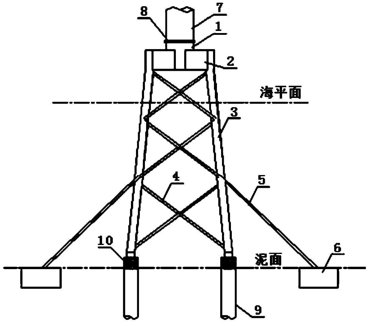
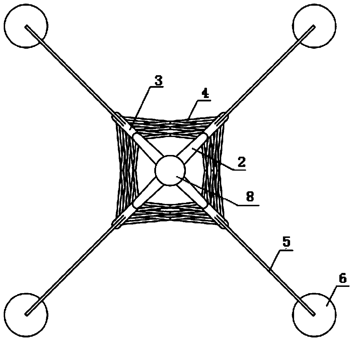
[0017] Such as figure 1 As shown, an offshore wind power composite foundation of the present invention includes a jacket, steel pipe piles 9, suction cylinder 6 and steel cables 5, the top of the jacket is provided with a top steel beam 2, and the top steel beam 2 is provided with a transition section 1, The bottom of the fan tower 7 is fixedly connected to the transition section 1 through a flange 8 or grouting to realize the fixed installation of the fan and the jacket. The bottom of the jacket is fixedly connected to the steel pipe pile 9 buried in the seabed. The bottom of the jacket is fixedly connected through the grouting section 10 to realize the fixed installation of the overall structure of the jacket on the seabed. A plurality of suction cylinders 6 are evenly distributed on the circumference centered on the fan tower 7 , and the p...


PUM


Abstract

The invention relates to an offshore wind power combination foundation. The offshore wind power combination foundation includes a guiding pipe frame, steel pipe piles, suction cylinders, and steel cables. The offshore wind power combination foundation is composed of the guiding pipe frame, the steel pipe piles, the suction cylinders, and the steel cables; the guiding pipe frame and the suction cylinders are connected by the steel cables, the steel cables can exert their high and strong tensile strength, the lateral rigidity of the combined foundation is increased, the guiding pipe frame bearsa vertical load, a fan horizontal load and a wave current force borne by the guiding pipe frame are transmitted to the suction cylinders through the steel cables for sharing, since the suction cylinders are dispersed and embedded into surface layer soil and have a large contact area with a surface layer soil foundation, horizontal force resistance of surface soil can be fully exerted, the horizontal bearing performance of a foundation pile can be improved, the basic anti-overturning capability is improved, the drawing force of main legs of the guiding pipe frame is reduced, thereby reducing the distance between the main legs of the guiding pipe frame and the cross section of a rod piece, and the basic cost and construction difficulty are reduced. The suction cylinders can employ negative pressure sinking, and the construction difficulty is small.

Description

technical field [0001] The invention relates to the technical field of offshore wind power fan foundations, in particular to an offshore wind power combined foundation. Background technique [0002] Rational development and utilization of wind energy has become the strategic fulcrum of the world's energy revolution. Offshore wind power in Europe has become an important part of its energy supply. China's offshore wind power is now being developed on a large scale, gradually developing towards seas with long offshore distances and deep waters. Invention Creating a wind turbine infrastructure suitable for water depths of 30-50m has become the top priority of domestic offshore wind power development. Due to the large load of wind turbines and the complex marine environment, how to make the basic structure of wind turbines safe, economical and applicable has become one of the main concerns in the industry. [0003] There are various types of foundation structures for offshore wi...

Claims


Application Information

Patent Timeline
Patent Type & Authority Applications(China)
IPC IPC(8): E02D27/42E02D27/52
Inventor 邹尤程卫民陶铁铃何杰曹龙付文军刘凯曾斌党莹颖张涛
Owner CHANGJIANG SURVEY PLANNING DESIGN & RES
Learn More