Novel mechanical arm of radial lifting mechanism of loading machine

A lifting mechanism and loader technology, applied in the direction of mechanically driven excavators/dredgers, etc., can solve the problems of complicated process, material spillage, and inability to ensure the leveling of the bucket, so as to avoid material spillage and solve the problem of overturning Effect

Pending Publication Date: 2019-06-07
NORTHEAST FORESTRY UNIVERSITY
View PDF1 Cites 2 Cited by
  • Summary
  • Abstract
  • Description
  • Claims
  • Application Information

AI Technical Summary

Problems solved by technology

At present, most of the market adopts the radial lifting form of the reverse six-bar mechanism, but it cannot guarantee the horizontal lifting of the bucket during the lifting process, so it will cause the material to spill, so most manufacturers and scholars are working on this problem. In the research, it is hoped that the bucket can be kept as flat as possible during the lifting process, and a large number of complex parameter optimization designs and structural designs have been carried out to avoid the occurrence of bucket overturning during the lifting process, but the process is quite complicated and difficult to achieve
[0003] Chinese Patent Publication No. CN 102296649 B, published on July 17, 2013, the name of the invention is a multi-link loading mechanism. The invention replaces the hydraulic transmission system with a multi-link mechanism, which overcomes the high maintenance cost of hydraulic excavators. Disadvantages, but the structure is too complicated, too many hinge points are not easy to maintain, it is difficult to ensure the assembly accuracy of the equipment during the manufacturing and assembly process, and it is impossible to ensure that the bucket remains flat during the lifting process

Method used


Image

  • Novel mechanical arm of radial lifting mechanism of loading machine
  • Novel mechanical arm of radial lifting mechanism of loading machine
  • Novel mechanical arm of radial lifting mechanism of loading machine

Examples


Embodiment Construction

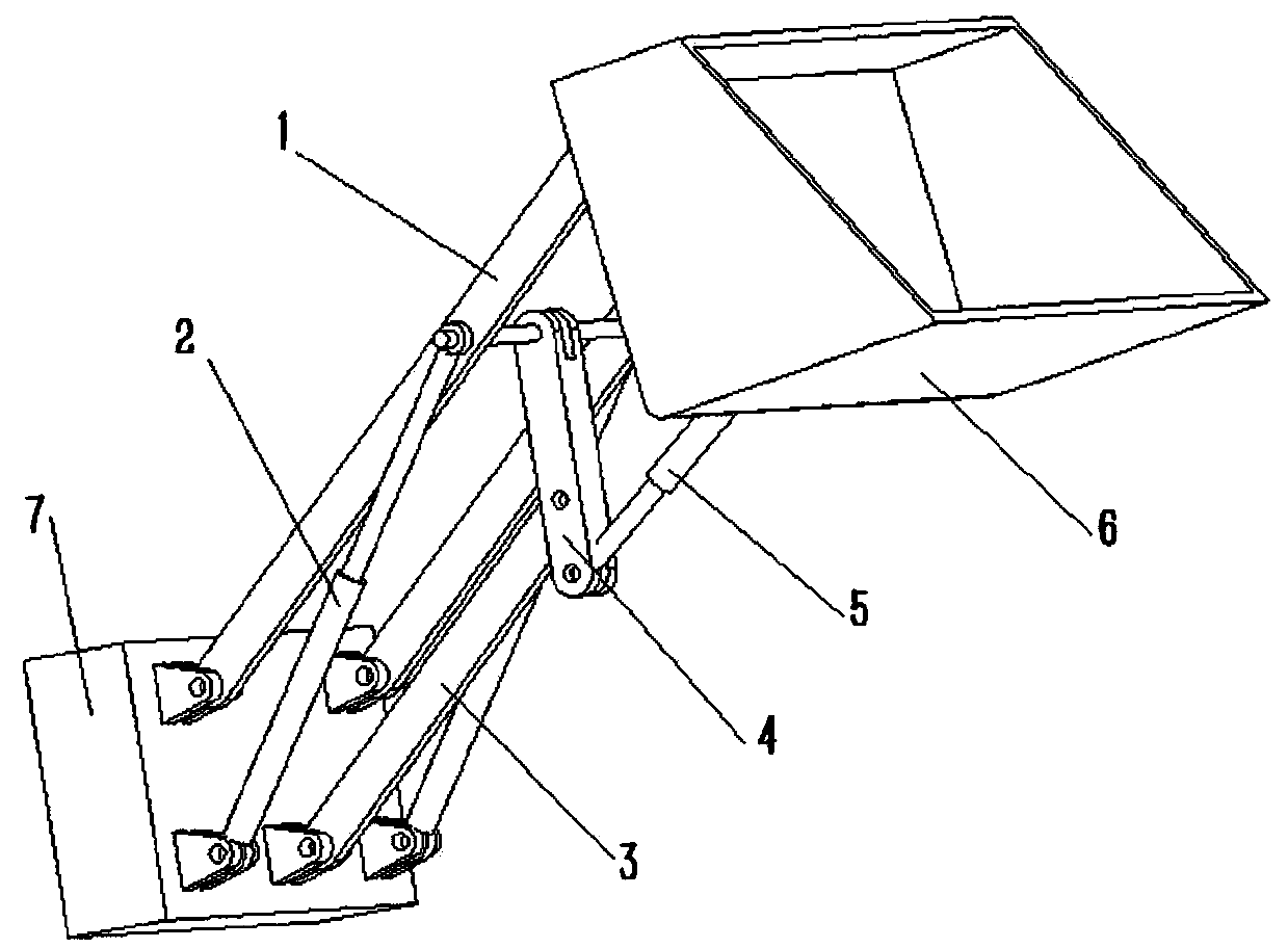
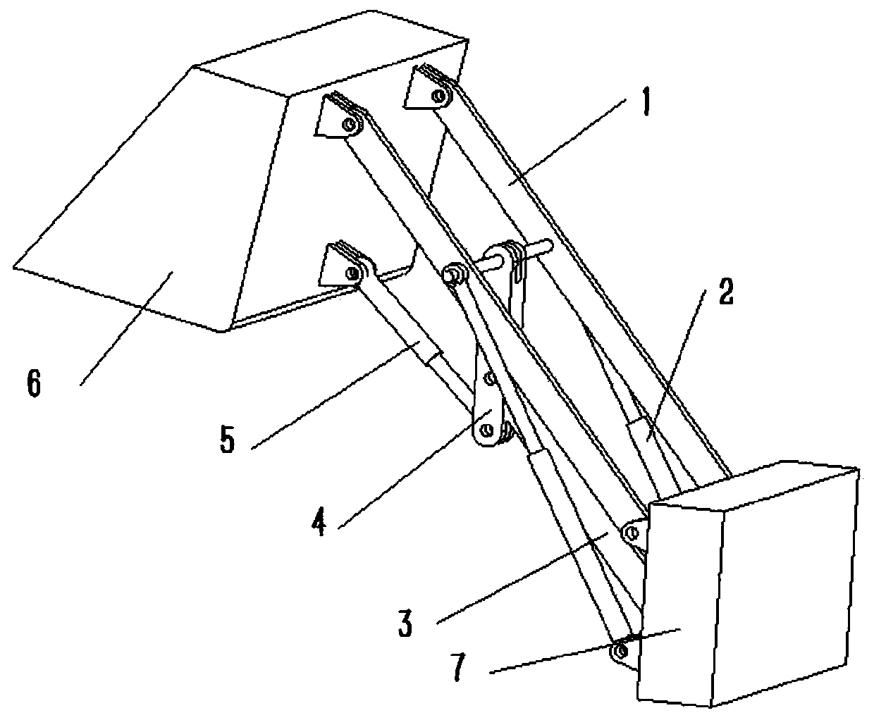
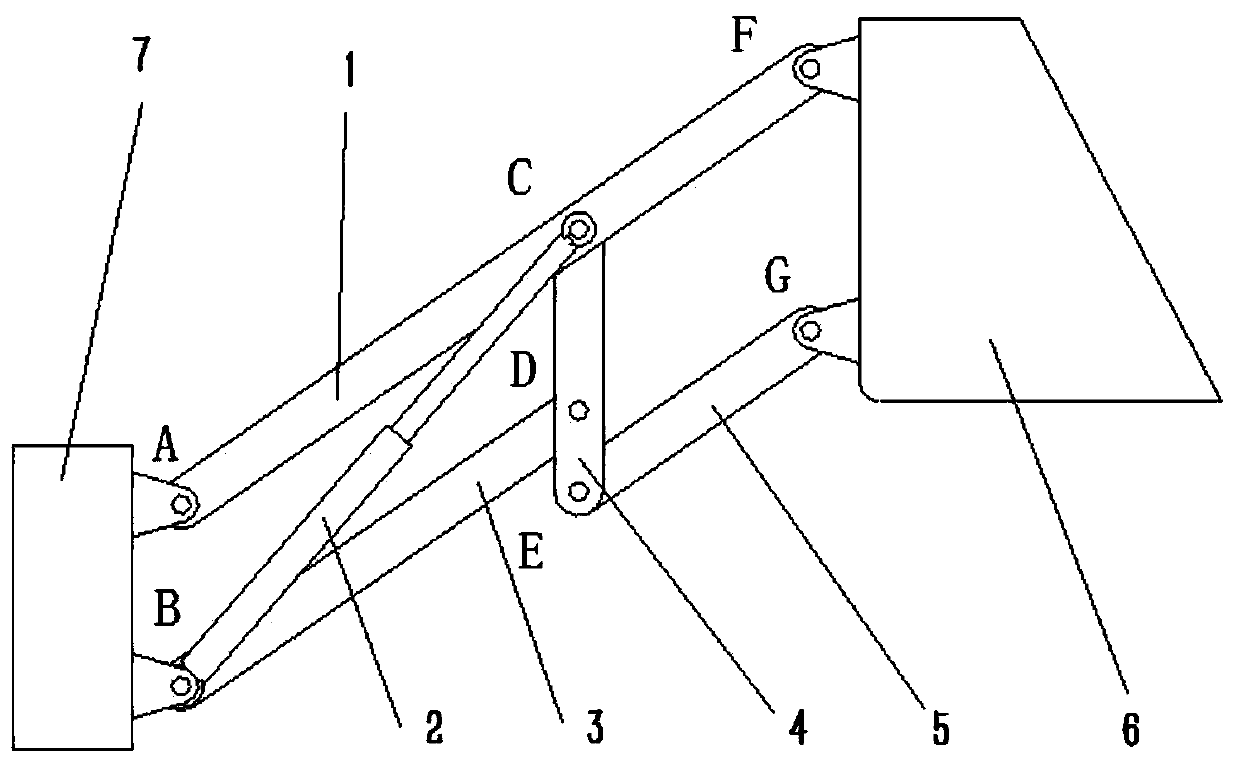
[0020] See figure 1 , figure 2 , image 3 , Figure 4 , Figure 5 , Image 6 , The present invention is a new type of loader radial lifting mechanism mechanical arm. The middle section of the big boom (1) has a cross beam for connecting the transition connecting rod (4); the new type of loader radial lifting mechanism mechanical arm is large The hinge pin at the rear end of the boom (1) is hinged to the upper part of the frame (7), and the front end is hinged to the upper part of the bucket (6). One end of the big boom hydraulic cylinder (2) is hinged to the lower part of the frame (7), and the other end is hinged to the frame (7). The middle section of the boom (1) is articulated, and the big boom hydraulic cylinder (2) provides lifting power to realize the lifting action of the bucket (6).

[0021] See figure 1 , figure 2 , image 3 , Figure 4 , Figure 5 , Image 6 , The new type loader radial lifting mechanism mechanical arm, the transition link (4) has three hinge points...


PUM


Abstract

The invention relates to a novel mechanical arm of a radial lifting mechanism of a loading machine. The mechanical arm is characterized in that the mechanical arm is composed of a frame, large movablearms, large movable arm hydraulic cylinders, a small movable arm, a transition connecting rod, a bucket hydraulic cylinder and a bucket. According to the novel mechanical arm of the radial lifting mechanism of the loading machine, the large movable arms are used as main lifting components, and lifting power is provided through the large movable arm hydraulic cylinders; the small movable arm is used for supporting the transition connecting rod, and the bucket hydraulic cylinders, the small movable arm and the large movable arms are connected through the transition connecting rod so that the target transmission effect is achieved; when pistons of the hydraulic cylinders are reversely rotated to extend out for a fixed length, the overall lifting mechanism defines parallelogram mechanisms connected in series; and it can be ensured that the bucket angle does not deflect in the lifting process of the mechanical arm. The novel mechanical arm is rational in structure; not only is the bucket prevented from being overturned according to the translational motion principle of the connecting rods of the parallelogram mechanisms, but also the design complexity of a vertical lifting mechanism isavoided, so that the performance of a traditional mechanical arm of the radial lifting mechanism is improved.

Description

Technical field: [0001] The invention relates to the field of loaders, in particular to a new type of radial lifting mechanism mechanical arm for loaders Background technique: [0002] The loader lifting manipulator mainly adopts two forms of radial lifting and vertical lifting. The radial lifting mechanism has a simple structure and low cost, and the vertical lifting mechanism has a high cost, which has a great impact on the design and layout of the frame, but the lifting The trajectory is not a completely vertical straight line, but a curve that approximates a straight line. At present, most of the market adopts the inverted six-bar mechanism for radial lifting, but it cannot guarantee that the bucket will be lifted horizontally during the lifting process, so materials will be scattered. Therefore, most manufacturers and scholars are addressing this problem. The research hopes to keep the bucket lifted as much as possible during the lifting process, and a lot of complex parame...

Claims


Application Information

Patent Timeline
Patent Type & Authority Applications(China)
IPC IPC(8): E02F3/34E02F3/36
Inventor 王枫辉王海滨
Owner NORTHEAST FORESTRY UNIVERSITY
Why Eureka
Try Eureka