Electric control silicon oil fan clutch

A clutch and silicone oil technology, applied in the direction of machine/engine, coolant flow control, engine components, etc., can solve the problems of low heat dissipation efficiency, short service life, slow response speed, etc., to reduce the processing process, facilitate later maintenance, The effect of speeding up the response

Pending Publication Date: 2019-06-07
长春宝成汽车电子有限公司
0 Cites 1 Cited by

AI-Extracted Technical Summary

Problems solved by technology

[0004] In order to solve the problems existing in the prior art, the present invention provides an electronically controlled silicone oil fan clutch, which solves the problems existing in the prior art by improving the o...

Abstract

The invention relates to the field of automobile engine cooling systems, in particular to an electric control silicon oil fan clutch. The clutch comprises a front cover, a shell, a driving shaft, a driven plate, a driving plate, valve blocks, a counting ring and a magnetic yoke coil, wherein the front cover and the shell are assembled through bolts and sealed to form an oil storage cavity, a working cavity and a flow channel; the driven plate is arranged on the driving plate; the driving plate is assembled on the driving shaft and is coaxial with the driving shaft; the driving shaft is arranged on a central shaft of the front cover and the shell, and assembled on the shell; the top end of the driving shaft is positioned in the front cover; the magnetic yoke coil is arranged around the driving shaft; the driving shaft is composed of a shaft body and a magnetic conduction column; the magnetic conduction column is positioned at the top end inside the shaft body; the shaft body and the magnetic conduction column are coaxially arranged; the two ends of the axis center of the driving plate are each provided with one valve block; one end of each valve block is arranged on the driving plate, and the other end of each valve block is away from the driving plate due to elasticity; corresponding to the lower part of each valve block, an oil inlet hole is formed in the driving plate; and the counting ring is arranged in the shell. According to the clutch, the service life of the clutch is prolonged, the cost is reduced, and the response speed is increased.

Application Domain

Technology Topic

Image

  • Electric control silicon oil fan clutch
  • Electric control silicon oil fan clutch
  • Electric control silicon oil fan clutch

Examples

  • Experimental program(1)

Example Embodiment

[0012] The present invention will be further described in detail below in conjunction with the drawings and embodiments.
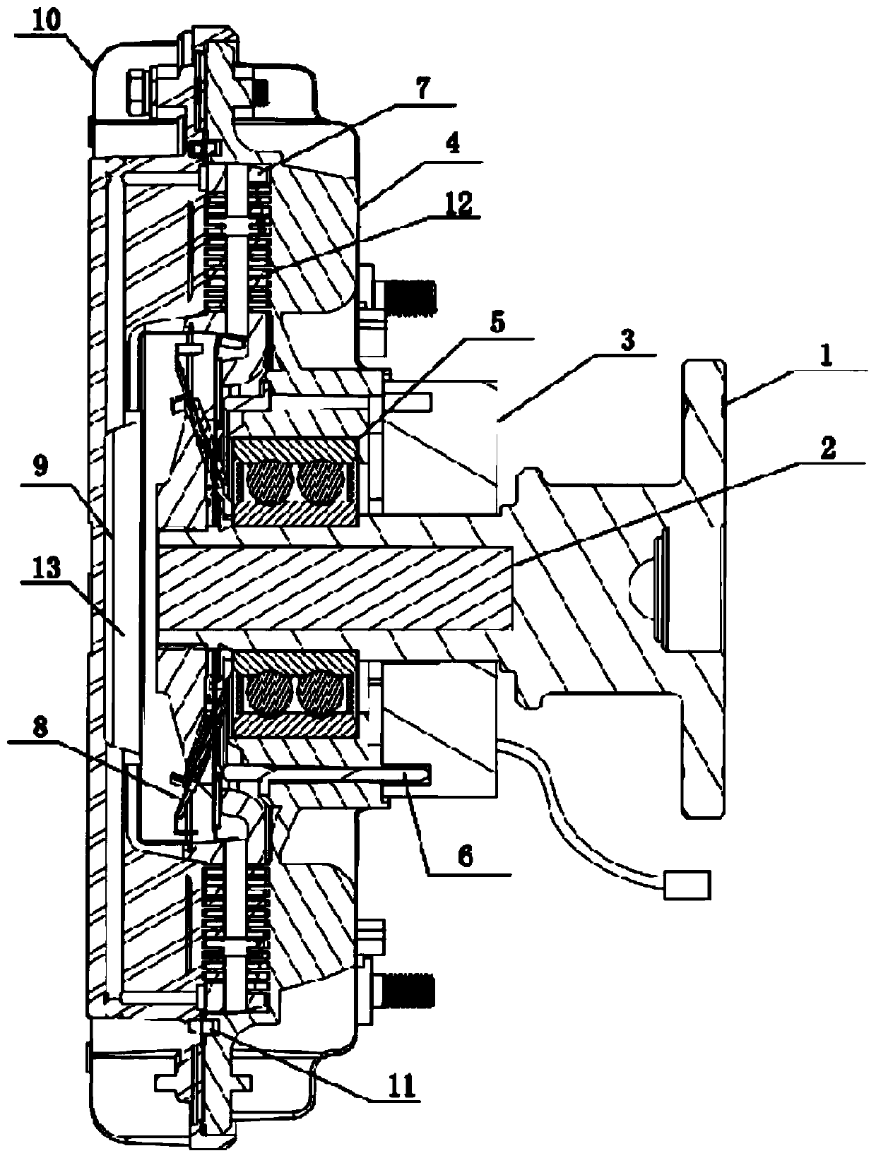
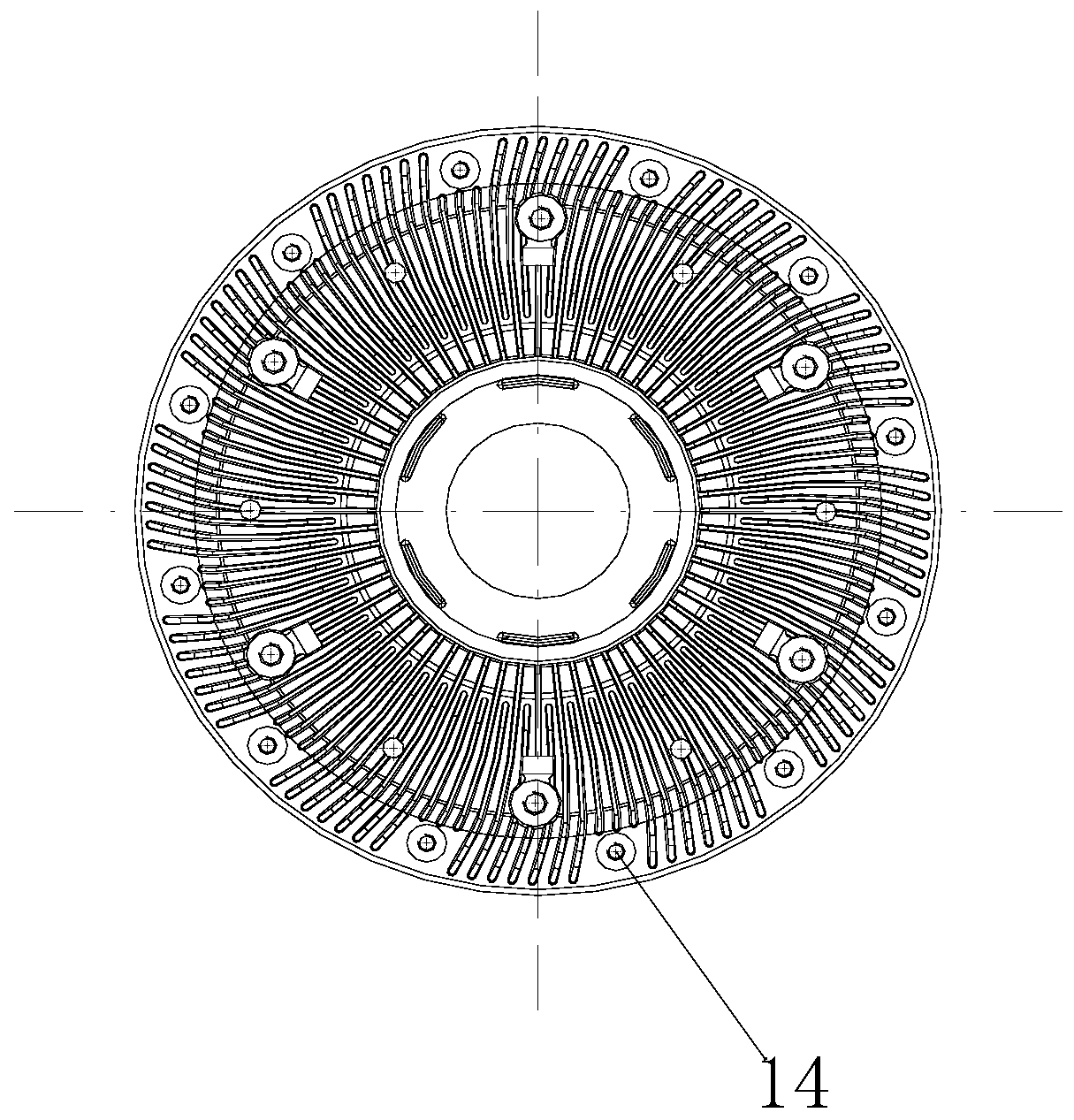
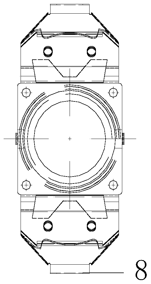
[0013] Such as figure 1 As shown, an electronically controlled silicon oil fan clutch includes: a driving shaft 1, a magnetic pole 2, a yoke coil 3, a housing 4, a bearing 5, a counting ring 6, a driving plate 7, a valve plate 8, and a driven Plate 9, front cover 10, sealing ring 11, working cavity 12 and oil storage cavity 13. Such as figure 2 As shown, the front cover 10 and the housing 4 are assembled by bolts 14, so that the maintenance in the middle and late stages of use is solved without affecting the seal, and the service life of the electronically controlled silicon oil fan clutch is also prolonged. The front cover 10 and the housing 4 are sealed by a sealing ring 11 to form an oil storage chamber 13, a working chamber 12, and a flow channel; the driven plate 9 is press-fitted on the driving plate 7 to realize the relationship between the oil storage chamber 13 and the working chamber 12 The drive plate 7 is assembled on the drive shaft 1 and arranged coaxially with the drive shaft 1, and is sealed with the front cover 11 to form an oil storage chamber 13, and sealed with the housing 4 to form a working chamber 12; The driving shaft 1 is arranged on the central axis of the front cover 10 and the housing 4, assembled on the housing 4 through the bearing 5, and its top end is located in the front cover 10, the yoke coil 3 is arranged around the driving shaft 1; the driving shaft 1 is composed of a shaft body and a magnetic column 2, the magnetic column 2 is located at the top end of the shaft body, the shaft body and the magnetic column 2 are coaxial Setting, the material of the shaft body is 45# steel, and the material of the magnetic column 2 is pure iron; the active shaft 1 made of 45# steel has more advantages in terms of the chemical structure of raw materials and the price and convenience of procurement. The carbon content of #steel is higher than that of pure iron, so the processed driving shaft 1 is also better in terms of hardness and wear resistance. 45# steel can be heat treated. After heat treatment, the driving shaft 1 can be hardened. And abrasion resistance has been further strengthened. Compared with pure iron, 45# steel has certain disadvantages in terms of magnetic permeability. In order to solve the problem of 45# steel’s inferior magnetic permeability of the drive shaft, special processing is carried out on one end of the drive shaft 1, and the pure iron is assembled in the manner of a mandrel. Go to the drive shaft 1 to solve the disadvantage of the relatively poor magnetic permeability of 45# steel. Through the above changes in materials, the design of pure iron core shafts is added, and the comparison with the pure iron drive shaft is further improved on the basis of maintaining better magnetic permeability. The hardness and wear resistance of the driving shaft 1; image 3 As shown, a valve plate 8 is provided at both ends of the axis of the active plate 7, and a corresponding valve plate 8 is added to solve the problem of limited silicone oil flow inside the existing single valve plate product. The double valve plate solves the problem The increase in the upper limit of the silicone oil flow rate increases the response speed of the fan clutch, and the generation of the fan clutch slip is correspondingly reduced. One end of the valve plate 8 is mounted on the active plate 7, and the other end is away from the active plate 7 due to elasticity. Corresponding to each valve plate 8, the active plate 7 has an oil inlet hole, and a counting ring 6 is provided in the housing 4 under each valve plate 8. The counting ring 6 and the housing 4 are integrally cast and formed, which saves machining errors generated in machining, and at the same time ensures the axial matching relationship between the counting ring 6 and the housing 4, improves the sealing performance and reduces leakage. A heat sink is provided on the outer surface of the front cover 10, and the heat sink is composed of a straight heat sink and an arc heat sink. The heat dissipation area of ​​the electronic controlled silicon oil fan clutch is increased, the impact with the air is reduced, and the airflow can be smoothly and smoothly guided through the surface of the heat sink. Compared with linear heat sinks, heat sinks with a certain curvature have a better guiding effect on air. Combining traditional linear heat sinks with curved heat sinks makes full use of the surface space of the front cover 10. It also has better heat dissipation and energy saving effects.
[0014] The working principle is as follows: When the ECU controls the yoke coil 3 to be energized, the active shaft 1 and the counting ring 6 conduct magnetic force in the magnetic field of the yoke coil 3, and the two valve plates 8 are attracted by the magnetic counting ring 6, and the active The two oil inlet holes on the plate 7 are sealed. At this time, the amount of silicone oil in the working chamber 12 is reduced, the torque of the active plate 7 in the working chamber 12 is reduced, the clutch is disengaged, and the fan is rotating at a low speed. When the ECU controls the yoke coil 3 to be de-energized, the magnetic field disappears, the valve plate 8 bounces under its own elastic action, and the oil inlet is in an open state. At this time, the silicone oil flows from the oil storage chamber 13 to the working chamber 12, as the amount of silicone oil increases. As the increase, the torque of the active plate 7 in the working chamber 12 increases, thereby driving the entire clutch to rotate at a high speed, and the fan speed also increases rapidly, realizing rapid cooling. This is repeated to achieve the purpose of air cooling and energy saving.

PUM

no PUM

Description & Claims & Application Information

We can also present the details of the Description, Claims and Application information to help users get a comprehensive understanding of the technical details of the patent, such as background art, summary of invention, brief description of drawings, description of embodiments, and other original content. On the other hand, users can also determine the specific scope of protection of the technology through the list of claims; as well as understand the changes in the life cycle of the technology with the presentation of the patent timeline. Login to view more.

Similar technology patents

Direct-connection magnetic coupling rotating shaft for electric spark forming machine

PendingCN114160898AEasy to maintain laterSimple installation and debuggingElectrical-based auxillary apparatusPhysicsVibration transmission
Owner:通用技术集团机床工程研究院有限公司 +1

Cable distribution device for intelligent community

Owner:铜陵百安科技股份有限公司

Classification and recommendation of technical efficacy words

  • Extended service life
  • Easy to maintain later

Community data system

Owner:QINGDAO PENGHAI SOFT CO LTD
Why Eureka
Try Eureka